Anti-sputtering material distributing valve adjustable in flow

An adjustable and anti-splash technology, applied in the direction of sliding valves, valve details, valve devices, etc., can solve problems such as waste and pollution, and achieve the effect of preventing liquid residue, realizing flow rate and reducing Reynolds coefficient

Active Publication Date: 2017-02-15
WUHAN INTELLIGENT EQUIP IND INST CO LTD
View PDF6 Cites 12 Cited by
  • Summary
  • Abstract
  • Description
  • Claims
  • Application Information

AI Technical Summary

Problems solved by technology

[0003] Aiming at the above defects or improvement needs of the prior art, the present invention provides an anti-sputter flow rate adjustable batching valve, which is controlled by the combination of the electric cylinder and the air cylinder to control the accuracy by stretching the cylinder and control the flow rate by lifting the electric cylinder Size, while satisfying the accuracy and speed of ingredients, it solves the problems of pollution and waste caused by liquid splash and residue. It has the advantages of anti-splash, anti-residue, adjustable flow rate, and high preparation accuracy. It is suitable for flavors, fragrances, and cigarette factories. And industries that require liquid raw material preparation

Method used


Image

  • Anti-sputtering material distributing valve adjustable in flow
  • Anti-sputtering material distributing valve adjustable in flow
  • Anti-sputtering material distributing valve adjustable in flow

Examples


Embodiment Construction

[0021] In order to make the object, technical solution and advantages of the present invention clearer, the present invention will be further described in detail below in conjunction with the accompanying drawings and embodiments. It should be understood that the specific embodiments described here are only used to explain the present invention, not to limit the present invention. In addition, the technical features involved in the various embodiments of the present invention described below can be combined with each other as long as they do not constitute a conflict with each other.

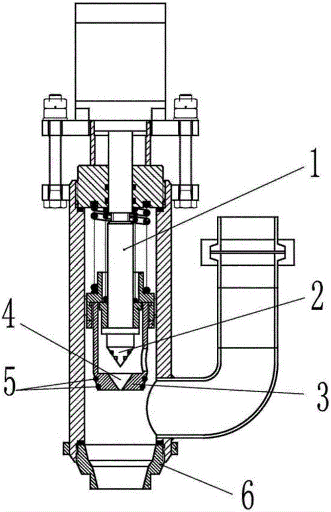
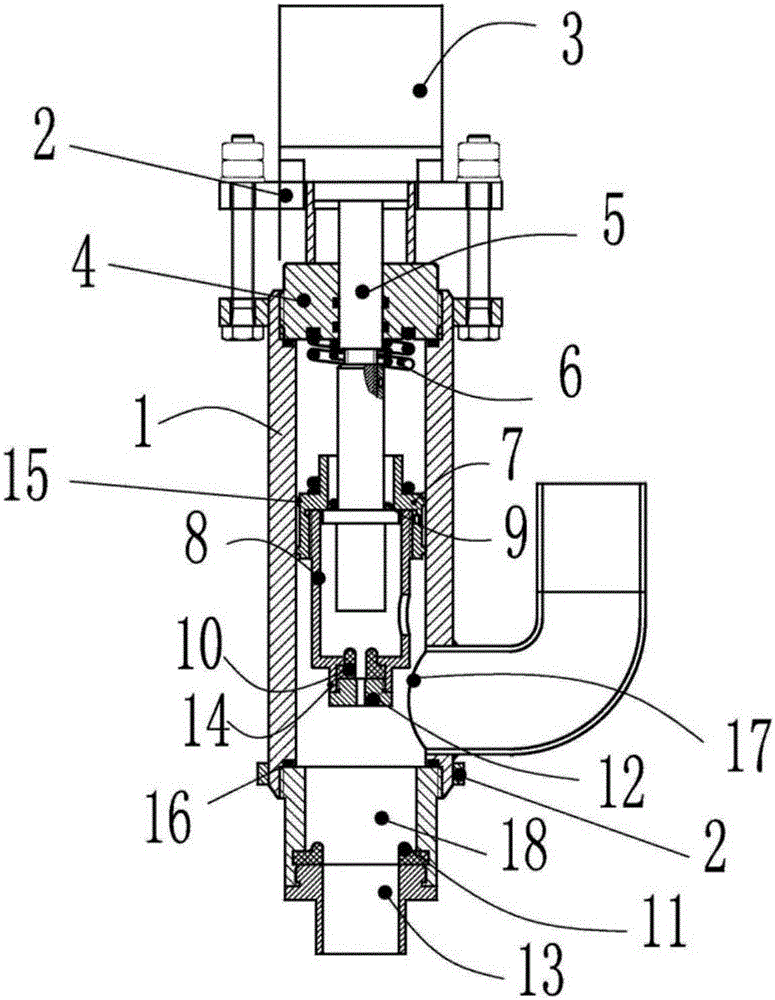
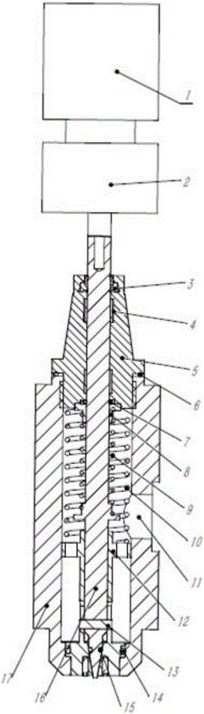
[0022] Such as image 3 As shown, the anti-splash flow adjustable batching valve provided by the embodiment of the present invention includes a valve core assembly and a power assembly, wherein the power assembly provides the required power for the movement of the valve core assembly, and the relevant components in the valve core assembly Driven by the power assembly, the components move up and...


PUM


Abstract

The invention discloses an anti-sputtering material distributing valve adjustable in flow. The anti-sputtering material distributing valve comprises a valve core assembly and a power assembly. The valve core assembly comprises an upper valve body, a lower valve body, a valve core and a middle valve core. The upper valve body is connected with the upper end of the lower valve body and is of a hollow structure. The lower valve body is of a hollow structure, the side surface of the lower valve body is provided with a feeding inlet for allowing liquid to enter, and the lower end of the lower valve body is provided with a plurality of cylindrical holes serving as large flow openings of the material distributing valve. The valve core is sequentially inserted into the hollow structure of the upper valve body and the hollow structure of the lower valve body from the upper end of the upper valve body, and a small spring is arranged between the valve core and the upper valve body. The middle valve core is arranged between the valve core and the inner wall of the lower valve body and slidably matched with the valve core, a large spring is arranged between the middle valve core and the upper valve body, and the lower end of the middle valve core is provided with a through hole matched with the lower end of the valve core and a plurality of cylinders closely matched with the cylindrical holes in the lower valve body. The power assembly is connected with the upper end of the valve core and used for driving the valve core and the middle valve core to move up and down. The anti-sputtering material distributing valve adjustable in flow has the advantages of being capable of preventing sputtering and residues and adjusting the flow, high in preparation precision and the like.

Description

technical field [0001] The invention belongs to the field of high-precision batching valves, and more specifically relates to an anti-sputtering flow-adjustable batching valve. Background technique [0002] At present, the following two types of batching valves are mainly used in the flavor and fragrance industry and cigarette factories: one is to use such as figure 1 The shown two-stage cylinder + two-stage conical on-off valve mainly controls the opening and closing of the two-stage conical valve through the three positions of the cylinder. When controlling the accuracy, the cylinder moves to the first position and lifts the first-stage valve. , when controlling a large flow, the cylinder moves to the second position and lifts the second stage. In this method, the shape of the valve mouth is conical. When preparing a large flow, the liquid will collide due to the divergence angle intersecting, resulting in liquid Splash around; the second is if figure 2 The shown two-po...

Claims


Application Information

Patent Timeline
Patent Type & Authority Applications(China)
IPC IPC(8): F16K3/22F16K3/314F16K31/12
CPCF16K3/22F16K3/314F16K31/12
Inventor 任振石文中
Owner WUHAN INTELLIGENT EQUIP IND INST CO LTD
Why Eureka
Try Eureka