A scraper conveyor with floating coal cleaning device

A technology of scraper conveyor and cleaning device, which is applied in the field of scraper conveyor, can solve the problems of lowering the transmission power, falling off, reducing the effective output power of the geared motor, etc., and achieves the advantages of easy cleaning, stable structure, and enhanced effective output power Effect

Active Publication Date: 2018-11-27
JIANGSU VOCATIONAL INST OF ARCHITECTURAL TECH
View PDF11 Cites 0 Cited by
  • Summary
  • Abstract
  • Description
  • Claims
  • Application Information

AI Technical Summary

Problems solved by technology

[0002] The scraper of the existing scraper conveyor generally adopts an L shape. When the items to be conveyed are too heavy, there is a problem that the scraper is bent and deformed to reduce the conveying power; the existing scraper conveyor generally uses Cement bonds the cast stone plate to the upper surface of the machine body to solve the wear problem of the scraper on the machine body, but there is still a problem that after a period of use, the cast stone plate falls off due to poor bonding, causing the wear problem of the machine body to be unresolved. Solve the problem that the maintenance workload of the existing scraper conveyor is large, the working efficiency is low and the service life is short. At the same time, when the existing scraper conveyor is working, it is easy to accumulate floating coal in the gap between the scraper and the working surface. It is extremely difficult to clean while increasing friction and reducing the effective output power of the geared motor

Method used


Image

  • A scraper conveyor with floating coal cleaning device
  • A scraper conveyor with floating coal cleaning device
  • A scraper conveyor with floating coal cleaning device

Examples


Embodiment 1

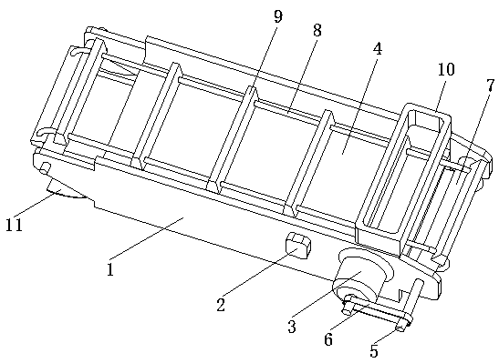
[0024] A scraper conveyor with a floating coal cleaning device, comprising two parallel side frame plates 1 and a wear-resistant bottom plate 4, the two side frame plates 1 are connected and fixed by a wear-resistant bottom plate 4 to form a U-shaped groove Structure; a feed hopper 10 is provided at the upper end of one side of the two side frame plates 1 , and a lower hopper 11 is provided at the lower end of the other side of the two side frame plates 1 .

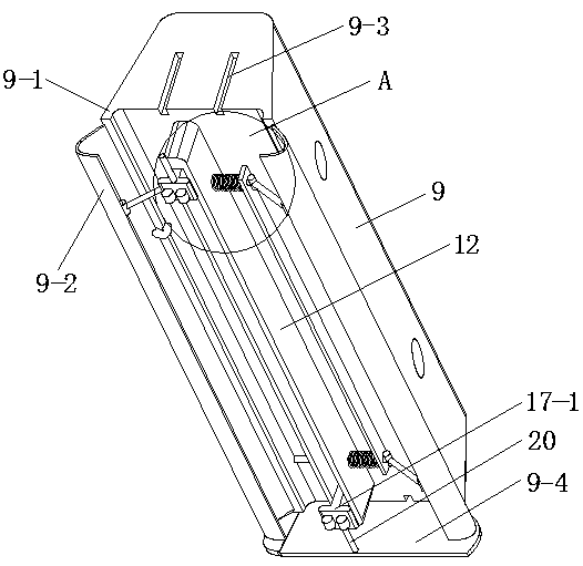
[0025] The shaft holes on the left and right sides of the side frame plate 1 are respectively provided with transmission shafts 5, and a roller 7 that is closely matched or integrally formed with it is arranged on the transmission shaft 5, and the two rollers 7 are connected by two chains 8. transmission, between the two chains 8 there are evenly arranged a plurality of scrapers 9 which are synchronously driven; the shaft end of the transmission shaft on the right side is connected with the output shaft of the reduction mo...

example example 2

[0031] A scraper conveyor with a floating coal cleaning device, comprising two parallel side frame plates 1 and a wear-resistant bottom plate 4, the two side frame plates 1 are connected and fixed by a wear-resistant bottom plate 4 to form a U-shaped groove Structure; a feed hopper 10 is provided at the upper end of one side of the two side frame plates 1 , and a lower hopper 11 is provided at the lower end of the other side of the two side frame plates 1 .

[0032] The shaft holes on the left and right sides of the side frame plate 1 are respectively provided with transmission shafts 5, and a roller 7 that is closely matched or integrally formed with it is arranged on the transmission shaft 5, and the two rollers 7 are connected by two chains 8. transmission, between the two chains 8 there are evenly arranged a plurality of scrapers 9 which are synchronously driven; the shaft end of the transmission shaft on the right side is connected with the output shaft of the reduction mo...

Embodiment 3

[0037]A scraper conveyor with a floating coal cleaning device, comprising two parallel side frame plates 1 and a wear-resistant bottom plate 4, the two side frame plates 1 are connected and fixed by a wear-resistant bottom plate 4 to form a U-shaped groove Structure; a feed hopper 10 is provided at the upper end of one side of the two side frame plates 1 , and a lower hopper 11 is provided at the lower end of the other side of the two side frame plates 1 .

[0038] The shaft holes on the left and right sides of the side frame plate 1 are respectively provided with transmission shafts 5, and a roller 7 that is closely matched or integrally formed with it is arranged on the transmission shaft 5, and the two rollers 7 are connected by two chains 8. transmission, between the two chains 8 there are evenly arranged a plurality of scrapers 9 which are synchronously driven; the shaft end of the transmission shaft on the right side is connected with the output shaft of the reduction mot...


PUM


Abstract

The invention discloses a scraper conveyor with a float coal cleaning device. The scraper conveyor comprises a bracket a feed hopper is arranged on one side of the bracket; a discharge hopper is arranged on the other side of the bracket; and multiple scrapers for pushing coals from the feed hopper to the discharge hopper and a transmission mechanism for driving the multiple scrapers are arranged in the bracket. The trapezoidal scraper structure is stable, and is more durable compared with a sheet shape; an elastic plate and a side cover plate are convenient to stop float coals, so that no float coals are below the scrapers; when the scrapers are suffered from the pressure, a spring I and a spring II are compressed, so that the scrapers move in the direction of a wear resisting baseplate; meanwhile, a movable shaft moves to the inner side; the bending degree of the elastic plate is increased; a gap between the elastic plate and the wear resisting baseplate is smaller; the float coals are stopped on the outer side of the elastic plate; when the pressure suffered by the scrapers is weakened or not generated, the deformation of the elastic plate is recovered, the float coals remained between the elastic plate and the wear resisting baseplate are ejected out for cleaning; and the effective output power of a speed reducing motor is directly enhanced through rolling friction of a rubber wheel.

Description

technical field [0001] The invention relates to the technical field of scraper conveyors, in particular to a scraper conveyor with a floating coal cleaning device. Background technique [0002] The scraper of the existing scraper conveyor generally adopts an L shape. When the items to be conveyed are too heavy, there is a problem that the scraper is bent and deformed to reduce the conveying power; the existing scraper conveyor generally uses Cement bonds the cast stone plate to the upper surface of the machine body to solve the wear problem of the scraper on the machine body, but there is still a problem that after a period of use, the cast stone plate falls off due to poor bonding, causing the wear problem of the machine body to be unresolved. Solve the problem that the maintenance workload of the existing scraper conveyor is large, the working efficiency is low and the service life is short. At the same time, when the existing scraper conveyor is working, it is easy to acc...

Claims


Application Information

Patent Timeline
Patent Type & Authority Patents(China)
IPC IPC(8): B65G19/22
CPCB65G19/22B65G2201/045
Inventor 付红赵武仇文宁解恒参张伯权国芳崔廷峰陶祥令涂强苗磊刚宗义江周磊崔宏斌
Owner JIANGSU VOCATIONAL INST OF ARCHITECTURAL TECH
Why Eureka
Try Eureka