Liquid output equipment and liquid output control method

A technology for outputting equipment and liquids, which is applied in beverage preparation devices, kitchen utensils, household utensils, etc., and can solve problems such as complex flushing trajectories and inability to make

Pending Publication Date: 2017-05-10
BUBBLE LAB CO LTD
View PDF9 Cites 9 Cited by
  • Summary
  • Abstract
  • Description
  • Claims
  • Application Information

AI Technical Summary

Problems solved by technology

[0006] In coffee sales places, faucets need to be set up to brew coffee for customers. Existing faucets can only operate in a single fixed flushing mode downwards, and cannot make complex flushing trajectories, such as the curved flushing that imitates hand-brewed coffee track

Method used


Image

  • Liquid output equipment and liquid output control method
  • Liquid output equipment and liquid output control method
  • Liquid output equipment and liquid output control method

Examples


Embodiment 1

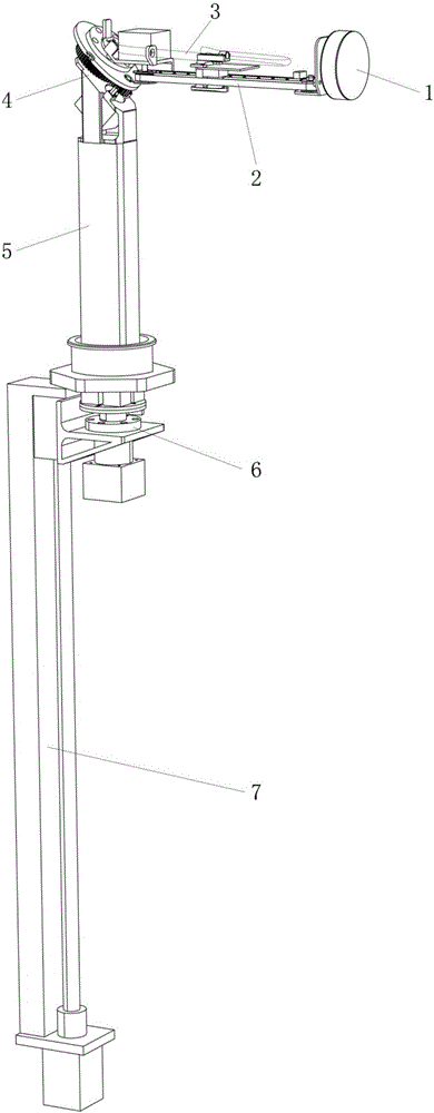
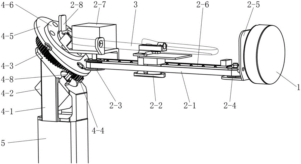
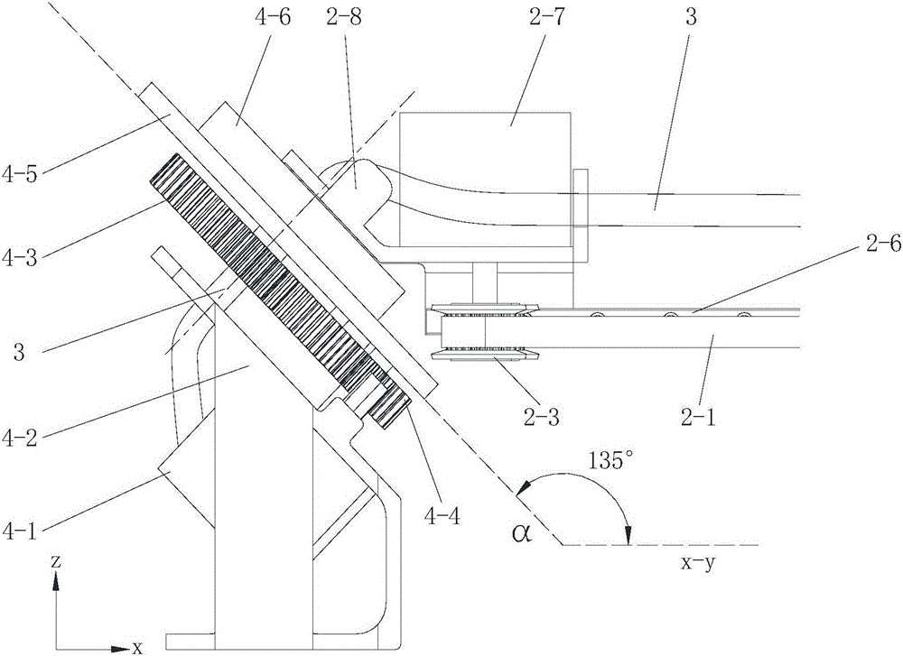
[0054] Such as figure 1 , figure 2 , image 3 Shown is Embodiment 1 of the present invention. In this embodiment, a liquid output device includes an upper body and a lower body. The upper body includes a first column 5 and a cantilever 2. The first column 5 and the cantilever 2 are jointed by angle adjustment. 4 connection combination; the first driving module and the water outlet module 2-2 are arranged on the cantilever 2, and the first driving module drives the water outlet module 2-2 to move along the length direction of the cantilever 2; the angle adjustment joint 4 is provided with a second Two driving modules, the second driving module drives the cantilever 2 to rotate, so that the cantilever 2 can be converted between horizontal and vertical positions; the lower body is provided with a third driving module 6, and the third driving module 6 passes through the first column 5 Supporting the upper body, the third driving module 6 drives the upper body to rotate around t...

Embodiment 2

[0078] Such as Figure 5 , Figure 6 Shown is Embodiment 2 of the present invention. In this embodiment, the difference from Embodiment 1 is that the second motor 4-2 is installed and fixed in the support 4-1, and the upper end of the second motor 4-2 is provided with a reducer 4-8, the reducer 4-8 is connected to the transmission mechanism through the universal joint 4-9, the universal joint 4-9 includes the active fork and the driven fork, the active fork is connected to the output shaft of the reducer 4-8, and the driven fork is vertical The installation panel of support 4-1 is installed, and connects the driving gear 4-4 in the transmission mechanism.

[0079]The driven fork has passed the mounting panel of the support 4-1, and a bearing needs to be installed at this position.

[0080] Perhaps this position is provided with an axle, and the installation panel installation of this axle vertical support 4-1. Driven fork connects the lower end of this axle, and driving gea...

Embodiment 3

[0085] In this embodiment, different from Embodiment 1, the synchronous drive mechanism includes two synchronous sprockets, the synchronous sprockets are respectively arranged on the first motor output shaft and the outer end fixed bracket, and the transmission chain is installed on the synchronous sprocket , the transmission chain is connected with the water outlet module.

[0086] The cross sections of the first column and the second column can be in various shapes such as rectangle, circle, ellipse, etc.

[0087] Other structures are the same as those in Embodiment 1, and will not be described again here.


PUM


Abstract

The invention discloses liquid output equipment, which solves the problems that the faucet cannot automatically rotate, the occupied space of the faucet above the table facet, and the faucet cannot folded and retracted and stored in the prior art. The liquid output equipment comprises an upper equipment body and a lower equipment body, the upper equipment body consists of a first stand column and a cantilever, and the first stand column and the cantilever are connected with a combination through angle adjustment joints; a first driving module and a water outlet module are arranged on the cantilever, and the first driving module drives the water outlet module to do reciprocating sliding along with the length direction of the cantilever; a second driving module is arranged on the angle adjustment joints and drives the cantilever to rotate, and the cantilever is changed between the horizontal position and the vertical position; and a third driving module for driving the upper equipment body to rotate is arranged on the lower equipment body. The liquid output equipment has the characteristics of being changeable in volume, flexible in structure, and capable of dynamically adjusting the motion trace of the water outlet module.

Description

technical field [0001] The invention relates to a liquid output device, which is used for automatic flushing when coffee, milk, solid drinks and other beverages are brewed. The invention also relates to a liquid output control method. Background technique [0002] Faucet is a very common household item in people's daily life, used to control the size and switch of water flow. In order to facilitate users to use hot water, the current faucet also has the function of mixing hot and cold water, so that hot or warm water can be used directly. [0003] A common faucet includes a water inlet and a water outlet, the water inlet is connected to a water pipe, and the water outlet stretches out through a cantilever and is suspended above the pool. For the convenience of receiving water, the position of the water outlet of some faucets is adjustable, but it is necessary to manually rotate the faucet, which brings a lot of inconvenience. [0004] The installation position of common f...

Claims


Application Information

Patent Timeline
Patent Type & Authority Applications(China)
IPC IPC(8): A47J31/46
CPCA47J31/46A47J2201/00
Inventor 郭垚鑫王江峰李永坡翟辉
Owner BUBBLE LAB CO LTD
Why Eureka
Try Eureka