
Tank realizing quantitative material discharging function
A quantitative discharge and discharge port technology, applied in the field of containers, can solve problems such as difficult to control the amount of seasoning
- Summary
- Abstract
- Description
- Claims
- Application Information
AI Technical Summary
Problems solved by technology
Method used
Image

Examples
Embodiment Construction
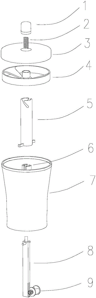
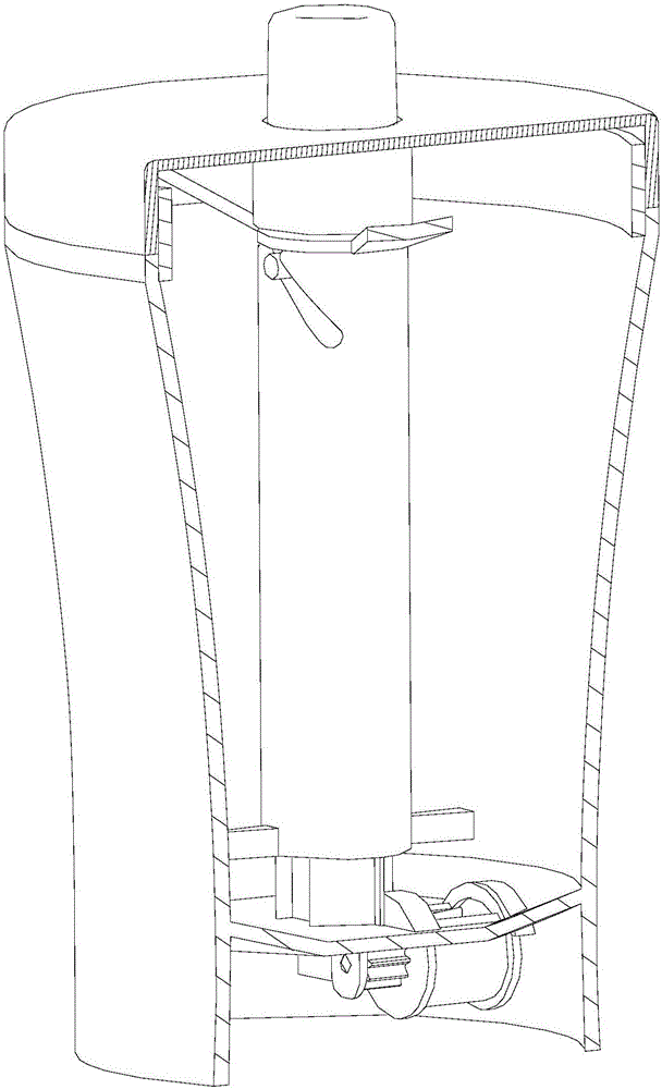
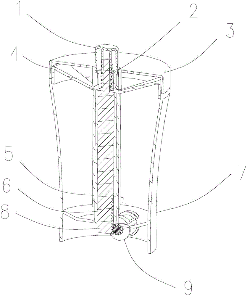
[0022] In order to describe the technical content, structural features, achieved goals and effects of the present invention in detail, the following will be described in detail in conjunction with the embodiments and accompanying drawings.
[0023] combine Figure 1 to Figure 3 As shown, the present invention discloses a quantitative discharge tank. This quantitative discharge tank includes a tank body 7, and the tank body 7 is used as the main body of the quantitative discharge tank, and is mainly used for storage of materials and maintenance of some mechanical components. Support or fix. A discharge port is provided at the bottom of the tank body 7, so that the material in the tank body 7 can be taken out from the discharge port. A rotatable hopper 9 is arranged at the discharge port, and a groove 15 is provided on the hopper 9, and the hopper 9 can be partially positioned at one side of the discharge port, and partially positioned at the other side of the discharge port, w...
PUM
 Abstract
Description
Claims
Application Information