Method for producing acoustic damping elements

An attenuating element, acoustic technology, applied in electrical components, sounding equipment, sensor parts, etc., can solve the problems of reproducibility, manufacturing cost and pollution process duration, achieve short development or processing time, small tolerance range, The effect of reducing the number of

Inactive Publication Date: 2017-05-10
SENNHEISER ELECTRONICS GMBH & CO KG
View PDF7 Cites 1 Cited by
  • Summary
  • Abstract
  • Description
  • Claims
  • Application Information

AI Technical Summary

Problems solved by technology

[0003] However, reproducibility, manufacturing costs and contamination as well as process duration are disadvantages in the methods applied so far

Method used


Image

  • Method for producing acoustic damping elements
  • Method for producing acoustic damping elements
  • Method for producing acoustic damping elements

Examples


Embodiment Construction

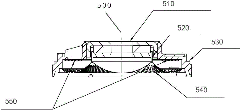
[0023] figure 1 A schematic cross-section of an electroacoustic transducer according to the invention is shown. The converter is designed, for example, as an earphone housing. Acoustic attenuation elements can be incorporated in the earphone housing. The coil 520 through which the current flows freely oscillates within the magnetic field generated by the electromagnetic system 510 and thus drives the membrane 540 fixedly connected thereto. Due to its mass and the spring stiffness of the membrane 540 , the system forms a freely oscillating spring-mass system, which has to be damped. This is done by means of an acoustic attenuation device 550 placed on the membrane 540, typically by means of a perforated membrane.

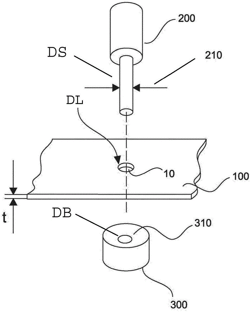
[0024] figure 2 A schematic diagram showing a method for fabricating an acoustic resistance. To produce the acoustic resistance for the damping element, a base material 100 is used and a plurality of holes 10 are punched into the base material. The punching of...


PUM

PropertyMeasurementUnit
diameteraaaaaaaaaa
pore sizeaaaaaaaaaa

Abstract

The invention relates to a method for producing acoustic damping elements having an acoustic resistance. For this purpose, at least one bushing (300) with a hole (310) having a diameter (DB) is placed below a base material (100). At least one hole (10) is punched into the base material (100) by means of at least one punch (200) having a punch diameter (DS). The punching process is repeated in different locations of the base material (100).

Description

technical field [0001] The invention relates to a method for producing an acoustic damping element. Background technique [0002] Acoustic attenuating elements with acoustic resistance are used in a variety of different electroacoustic devices, such as earpieces, microphones, headphones, acoustic transducers, and the like. Acoustic resistance can be fabricated from paper, wool, fabric, foam, cellular structures, plastic, metal and wire. These materials can have different acoustic resistances. The acoustic resistance can be set, for example, by providing holes in the applied material. The holes can be laser-drilled or etched into the material, for example. Alternatively, holes can also be drilled into the corresponding material. [0003] However, in the methods applied so far, reproducibility, manufacturing costs and contamination as well as process duration are disadvantages. [0004] In the German patent application claiming priority, the German Patent and Trademark Of...

Claims


Application Information

Patent Timeline
Patent Type & Authority Applications(China)
IPC IPC(8): B21D28/26B26F1/02B26F1/14B26F1/24G10K11/00B21D53/80
CPCB21D28/265B21D53/80B26F1/02B26F1/14B26F1/24G10K11/002G10K11/162H04R1/2876
Inventor 本杰明·罗斯罗伯特·科内特斯基布克哈德·马尔克曼
Owner SENNHEISER ELECTRONICS GMBH & CO KG
Why Eureka
Try Eureka