Generator for a power plant

A technology for generators and power plants, applied in the direction of machines/engines, components of pumping devices for elastic fluids, liquid fuel engines, etc., to achieve the effect of reasonable cost and simple structure

Inactive Publication Date: 2017-05-17
SIEMENS AG
View PDF7 Cites 1 Cited by
  • Summary
  • Abstract
  • Description
  • Claims
  • Application Information

AI Technical Summary

Problems solved by technology

The limitation is caused by the heating of the tabs due to resistance

Method used


Image

  • Generator for a power plant
  • Generator for a power plant
  • Generator for a power plant

Examples


Embodiment Construction

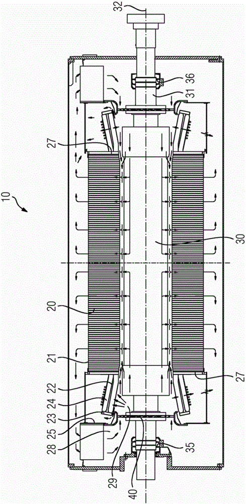
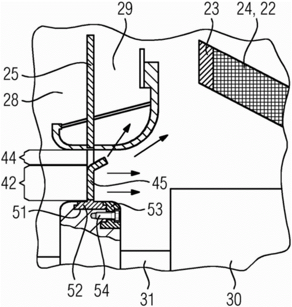
[0027] exist figure 1 A generator 10 for a power plant is shown in . The generator has a stator 20 in which a rotor 30 is arranged. The rotor 30 has a drive shaft 31 which is rotatably mounted on two bearings 35 , 46 . Center axis 32 runs through drive shaft 31 of rotor 30 . The stator 20 is covered on both sides by a separating plate 25 . The stator 20 has a stator body 21 from which an electrical conductor 22 emerges at an end face 27 and forms a winding head 24 . To connect the conductors 22 , at the ends there are provided webs 23 via which two adjacent conductors 22 are connected to one another in the winding head 24 .

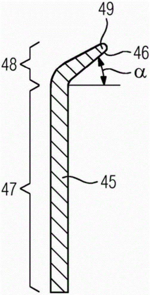
[0028] Fastened to the rotor 30 is a fan 40 which, in the simple embodiment shown, has fan blades 45 as in figure 2 It is fixed on the drive shaft 31 of the rotor as shown in . The fan blades 45 are distributed evenly over the circumference of the drive shaft 31 and extend in one plane together with the partition plate 25 , which laterally delimits...


PUM


Abstract

The invention relates to a generator (10) for a power plant, and to a method for cooling said generator. The generator comprises a stator (20) and a rotor (30), said stator (20) carrying conductors (22). The conductors (22) for a winding overhang (24) at least at one end of the stator (20) and the generator (10) has a fan (40) for cooling said winding overhang (24). The fan (40) produces a cooling air flow directed onto the winding overhang (24) and having an axial component and a radial component.

Description

technical field [0001] The invention relates to a generator for a power plant according to the preamble of claim 1 and a method for cooling a generator according to the preamble of claim 11 . Background technique [0002] In turbogenerators, the connection between the individual bars of the stator takes place by means of so-called winding heads. In the winding head, the rods are guided in the tangential direction as well as in the radial direction, so that the rods to be connected lie side by side at the ends of the winding head. The rods must be electrically connected to one another, wherein the connection can be performed in different ways. On the one hand, there is the possibility of connecting individual sub-conductors of one rod to sub-conductors of a second rod, which is referred to as sub-conductor interconnection. On the other hand, there is the possibility of combining the partial conductors of a rod into bundles and connecting the bundles with bundles of mating r...

Claims


Application Information

Patent Timeline
Patent Type & Authority Applications(China)
IPC IPC(8): H02K9/08
CPCH02K9/08F04D19/002F04D29/384H02K1/20H02K3/24H02K7/1807H02K9/06
Inventor 扬-亨里克·布拉姆克里斯托夫·埃弗斯西蒙·格茨埃斯特班·格劳索尔亚拉因奥利弗·哈伯雷尔马库斯·哈格多恩克里斯蒂安·耶克尔马里奥·克贝马蒂亚斯·科瓦尔斯基奥默·姆尔库利奇马库斯·默尔德斯卡罗琳·席尔德
Owner SIEMENS AG
Why Eureka
Try Eureka