Machining device and method for steel channel grooving and bending combined assembly

A processing device and assembly technology, which is applied in metal processing equipment, forming tools, manufacturing tools, etc., can solve the problems of slotting position and dimensional accuracy that are difficult to meet the requirements, affect the quality of assemblies, and reduce cutting efficiency. Processing accuracy and follow-up process, avoiding burrs and uneven incisions, and improving processing quality

Active Publication Date: 2017-05-31
马鞍山市欧姆科技发展有限公司
View PDF12 Cites 4 Cited by
  • Summary
  • Abstract
  • Description
  • Claims
  • Application Information

AI Technical Summary

Problems solved by technology

[0006] The purpose of the present invention is to overcome the problem that in the prior art, gas cutting is usually used to cut the grooves on the channel steel and then bend them, resulting in low cutting efficiency, poor cutting quality, and difficulty in satisfying the position and dimensional accuracy of the grooves. requirements, thereby affecting the quality of the final assembly, a processing device and processing method for channel steel slotted and bent assemblies are provided

Method used


Image

  • Machining device and method for steel channel grooving and bending combined assembly
  • Machining device and method for steel channel grooving and bending combined assembly
  • Machining device and method for steel channel grooving and bending combined assembly

Examples


Embodiment 1

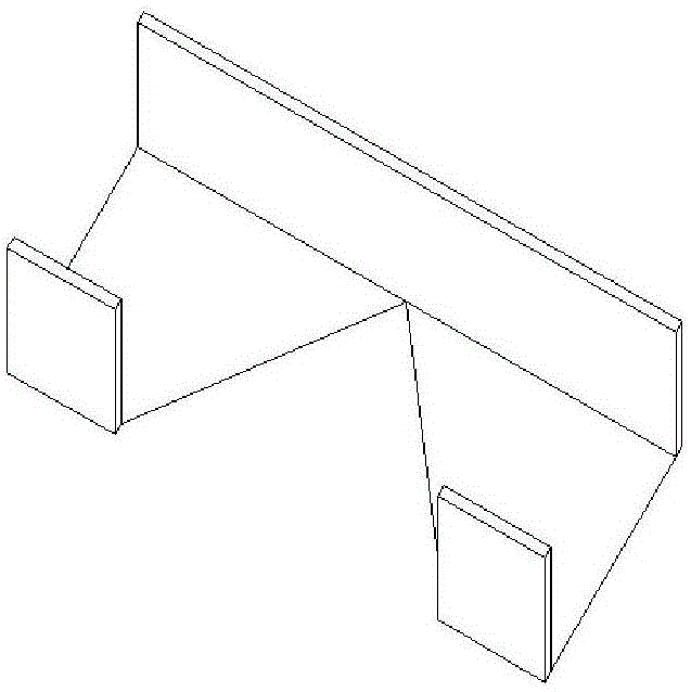
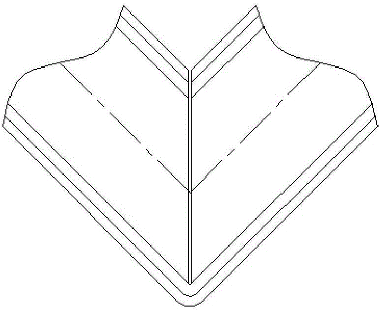
[0052] In conjunction with the accompanying drawings, a channel steel grooving and bending assembly processing device of this embodiment includes a rectangular grooving processing die, a triangular grooving processing die and a bending processing die, and the rectangular grooving processing die is placed on the side of the channel steel 5 Process a rectangular grooving, process a triangular grooving at the bottom surface of the channel steel 5 by the triangular grooving processing mold, thereby realize the processing of the upper grooving of the channel steel as shown in Figure 1, significantly improve the processing efficiency and the efficiency of the channel steel assembly The processing quality can avoid the phenomenon of burrs and uneven incisions, and ensure that the quality of the final assembly meets the requirements; the channel steel after grooving is bent through the bending processing mold.

[0053] Figure 1- Figure 5 As shown, the rectangular grooving mold of the...

Embodiment 2

[0057] A channel steel grooving and bending assembly processing device in this embodiment includes a rectangular grooving processing die, a triangular grooving processing die and a bending processing die, wherein:

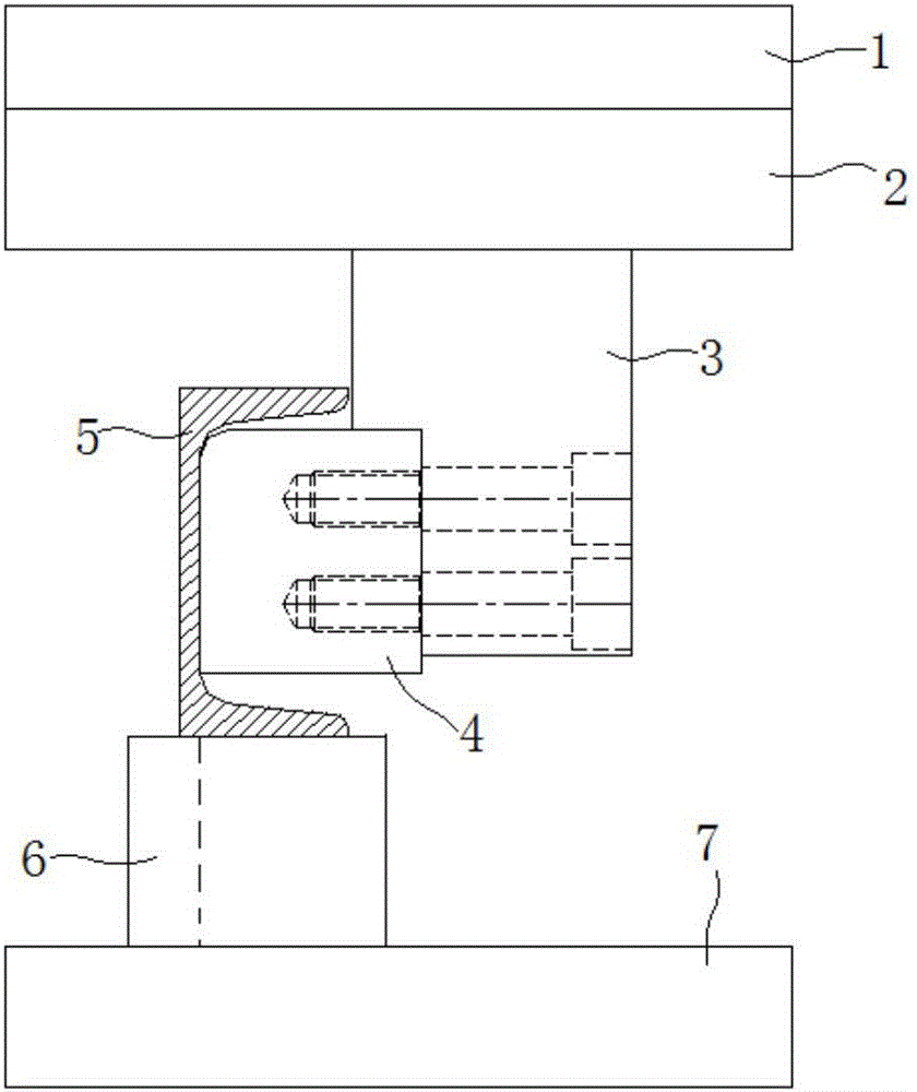
[0058] Such as Figure 2-Figure 5 As shown, the rectangular grooving processing mold includes a first moving knife 4 and a first static knife 8, the first moving knife 4 is processed into a cuboid structure and is positioned above the first static knife 8, and the first static knife 8, the first moving knife The knives 4 are all made of 9CrSi material with a hardness of HRC=55-57, which can effectively ensure the strength and toughness requirements of the knives, prevent the knives from breaking and deforming during the shearing process, and prolong the service life of the knives. Among them, as shown in Figure 1, in this embodiment, the first movable knife seat 3 is processed with a positioning groove, and the side of the first movable knife 4 is installed in the ...

Embodiment 3

[0067] The structure of the device for processing grooved and bent assembly of channel steel in this embodiment is the same as that in Embodiment 2.

[0068] A method for processing channel steel slotting and bending assemblies in this embodiment includes installing the rectangular grooving dies, triangular grooving dies and bending dies on the machine tool respectively, wherein the first static knife seat 6 and the second static knife seat 10 are installed on the machine tool table through the first lower template 7 and the second lower template 9 respectively, and the first movable knife seat 3 and the second movable knife seat (omitted in the figure) respectively pass through the first upper The template 2 and the second upper template (omitted in the figure) are fixedly connected with the connecting plate 1 on the machine tool. Firstly utilize the rectangular grooving processing die to process a rectangular slot on the side of the channel steel 5 to be processed, then use ...


PUM

PropertyMeasurementUnit
radiusaaaaaaaaaa
hardnessaaaaaaaaaa

Abstract

The invention discloses a machining device and method for a steel channel grooving and bending combined assembly and belongs to the technical field of shearing and bending machining. The machining device comprises a rectangular groove cutting machining mold, a triangular groove cutting machining mold and a bending machining mold, wherein the rectangular groove cutting machining mold comprises a first movable cutter and a first fixed cutter; the first movable cutter is fixedly connected with a first movable cutter base, and the shearing edge face of the first movable cutter is a V-shaped face with the middle portion sunken downwards; the first fixed cutter is installed on a first fixed cutter base and forms a "rightward-right-angle-u-shaped" structure; the triangular groove cutting machining mold comprises a second fixed cutter and a second movable cutter; the second movable cutter is fixedly connected with a second movable cutter base; the shearing edge face of the second movable cutter is a plane inclined to the other side from the position of a sharp corner of the plane; and the second fixed cutter is installed on a second fixed cutter base and forms an "L-shaped" structure. By adopting the machining device to perform grooving and bending machining on steel channels, the machining efficiency and the machining quality can be remarkably improved, and the precision and the quality of the combined assembly are made to meet the using requirements.

Description

technical field [0001] The invention belongs to the technical field of shearing and bending, and more specifically relates to a processing device and method for a channel steel slotted and bent assembly. Background technique [0002] Channel steel is a long strip of steel with a groove-shaped cross-section. Channel steel is a carbon structural steel for construction and machinery. It is a section steel with a complex cross-section. Mechanical equipment and vehicle manufacturing, etc. Channel steel has a wide range of uses, and in some special occasions in actual production, it is necessary to process such as Figure 1a The groove shown, then bend the channel steel along the center line of the groove, and finally weld the gap between the grooves after bending to get the following Figure 1b Assemblies shown. [0003] Due to the complex structure of the channel steel, in the prior art, gas cutting is usually used to cut each side of the groove on the channel steel in Fig. T...

Claims


Application Information

Patent Timeline
Patent Type & Authority Applications(China)
IPC IPC(8): B21D28/14B21D37/10B21D35/00
CPCB21D28/14B21D35/002B21D37/10
Inventor 芮春平
Owner 马鞍山市欧姆科技发展有限公司
Why Eureka
Try Eureka