Bamboo-shaped round bar energy-dissipating rod

A technology of bamboo-shaped and energy-dissipating rods, which is applied in the direction of building types, buildings, and building components, can solve the difficulties in setting up dense concrete and unbonded materials, the bamboo-shaped buckling restraint support is prone to torsional deformation, and the hysteresis curve is not good. Symmetry and other issues, to achieve the effect of simple structure, small yield force, and improved low cycle fatigue performance

Active Publication Date: 2018-11-16
SOUTHEAST UNIV
View PDF1 Cites 3 Cited by
  • Summary
  • Abstract
  • Description
  • Claims
  • Application Information

AI Technical Summary

Problems solved by technology

[0005] The present invention aims to solve the difficulty of setting concrete dense and unbonded materials in the buckling restraint support of steel and concrete combined restraint parts and the influence on performance, and at the same time, the bamboo buckling restraint support is prone to torsional deformation under pressure, and the consumption of the infinite section Energy rods have problems such as asymmetrical hysteresis curves and low energy dissipation performance caused by the slippage of external restraint parts. A new bamboo-shaped round rod energy dissipation rod with a limiting section is proposed.

Method used


Image

  • Bamboo-shaped round bar energy-dissipating rod
  • Bamboo-shaped round bar energy-dissipating rod
  • Bamboo-shaped round bar energy-dissipating rod

Examples


Embodiment 1

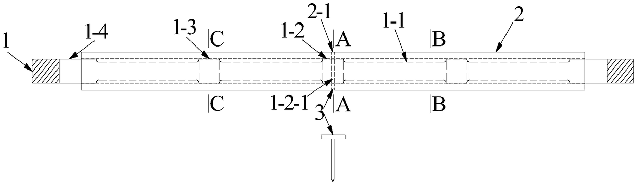
[0050] Such as Figure 1-9 Shown: a bamboo-shaped round rod energy-dissipating rod includes a core component 1, an outer constraint component 2 and a positioning pin 3;

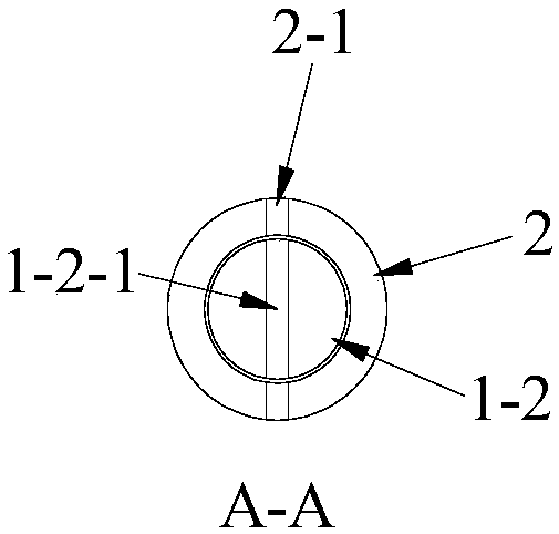
[0051] The core component 1 is composed of a plurality of energy dissipation sections 1-1, a middle limiting section 1-2, a bamboo section 1-3 and two end connecting sections 1-4 connected along a longitudinal coaxial line, and the middle limiting section 1 -2 is located in the middle of the core component 1, the bamboo section 1-3 is spaced apart from the energy dissipation section 1-1, arranged on both sides of the middle limiting section 1-2, and forms a whole with the middle limiting section 1-2 , the outer two ends are fixedly connected to the connecting sections 1-4 at both ends to jointly form the core component 1; the cross-sections of the middle limiting section 1-2, the bamboo section 1-3 and the connecting sections 1-4 at both ends are all circular , the middle of the middle limit section 1-2 has ...

Embodiment 2

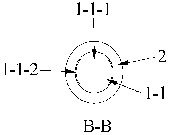
[0056] Such as Figure 10-20 Shown: this embodiment is the same as the rest of embodiment 1, the difference is that the distance between the two parallel opposite sides 1-1-1 of the plurality of energy dissipation sections 1-1 of the core component 1 is changed from the distance between the two sides of the core component 1 tapering off toward the middle.


PUM


Abstract

The invention discloses a bamboo-shaped round rod energy consumption rod comprising a core part, an outer restraint part and a locating pin. The core part is composed by connecting a plurality of energy dissipation sections, intermediate limiting sections, bamboo sections and two-end connecting sections along the longitudinal coaxial axis. The intermediate limiting sections are located in the middle of the core part. The bamboo sections and the energy dissipation sections are distributed at intervals, arranged on the two sides of the intermediate limiting sections and form a whole together with the intermediate limiting sections, and the two ends of the outer sides of the bamboo sections and the energy dissipation sections are fixedly connected with the two-end connecting sections to form the core part. The cross sections of the intermediate limiting sections, the bamboo sections and the two-end connecting sections are all circular. First holes are formed in the middles of the intermediate limiting sections in the diameter direction. The energy dissipation sections are manufactured by cutting of round rods in the length direction, so that the cross sections of the energy dissipation sections are two parallel opposite sides, the other two short sides are original arc lines, under the effect of the axial tensile pressure, the energy dissipation sections of the core part enter yielding through the formed new cross section areas, while the intermediate limiting sections, the bamboo sections and the two-end connecting sections always remain elastic.

Description

technical field [0001] The invention belongs to the field of civil engineering and relates to a buckling constraint support for reducing the seismic response of engineering structures. Background technique [0002] When cities and their buildings encounter strong earthquakes, not only will structural damage occur, but secondary disasters such as fires will also occur, which will trigger a series of chain disaster reactions. Based on this, the concept of energy dissipation and shock absorption proposed by the researchers aims to effectively reduce the seismic response of the structure by installing energy dissipation devices in the structure to absorb and dissipate energy, thereby avoiding serious damage to the main part of the structure. Mild steel damper is an energy-dissipating and shock-absorbing component with superior performance. It has been rapidly popularized and applied in developed countries such as Japan and the United States. However, the research and application...

Claims


Application Information

Patent Timeline
Patent Type & Authority Patents(China)
IPC IPC(8): E04H9/02E04B1/98
CPCE04H9/021
Inventor 王春林刘烨
Owner SOUTHEAST UNIV
Why Eureka
Try Eureka