Moving magnet type loudspeaker

A loudspeaker and moving magnet technology, applied in the direction of sensors, loudspeakers, electrical components, etc., can solve the problems of difficult to improve the high-frequency transient response of moving-coil speakers, unable to meet performance requirements, and low high-frequency performance , to achieve the effect of improving the poor transient response of high frequency, enhancing the force and high sensitivity

Active Publication Date: 2017-05-31
GOERTEK INC
View PDF17 Cites 4 Cited by
  • Summary
  • Abstract
  • Description
  • Claims
  • Application Information

AI Technical Summary

Problems solved by technology

At present, the speakers used in portable electronic devices are mostly dynamic speakers. The working principle of the dynamic speaker is that the electrified voice coil is affected by the Ampere force in the magnetic field, which drives the diaphragm to vibrate and produce sound. Due to its principle, the dynamic It is difficult to improve the high-frequency transient response of high-frequency speakers, and the high-frequency performance is low, which cannot meet the performance requirements of current Hi-Fi (high-fidelity) equipment.

Method used


Image

  • Moving magnet type loudspeaker
  • Moving magnet type loudspeaker
  • Moving magnet type loudspeaker

Examples


Embodiment 1

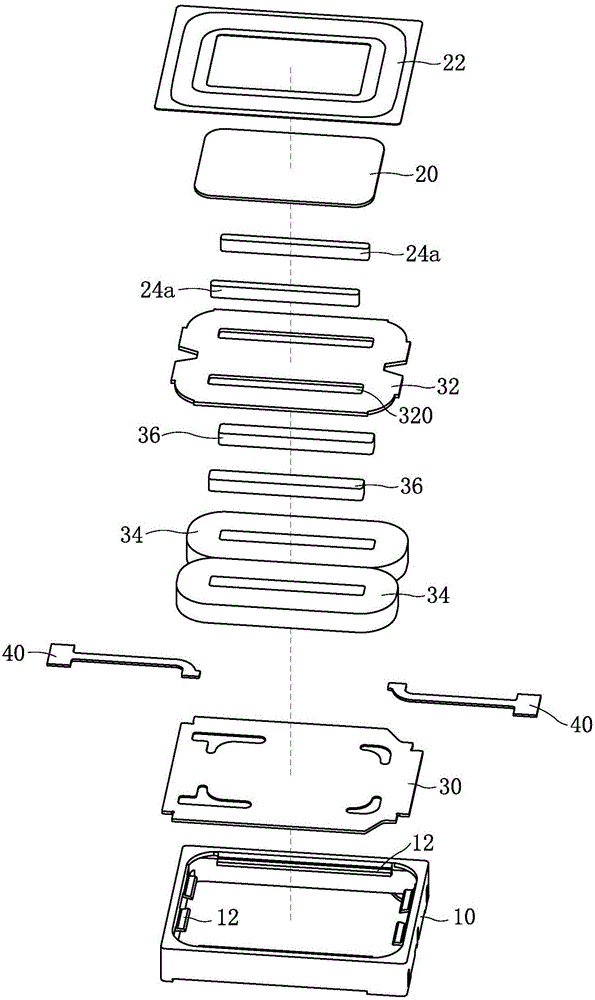
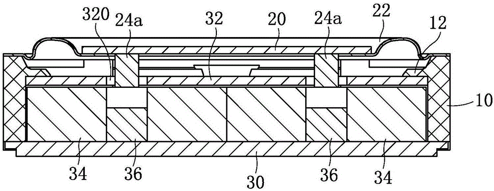
[0034] Such as figure 1 and figure 2 Commonly shown, a moving magnet loudspeaker has a rectangular parallelepiped structure and includes a rectangular ring-shaped housing 10 with openings at both upper and lower ends. The casing 10 contains a diaphragm and a voice coil 34 arranged parallel to the diaphragm, and a drive magnet 24a is fixed on the side of the diaphragm close to the voice coil 34; the voice coil 34 forms an electromagnet after being energized, and interacts with the drive magnet 24a The force-driven diaphragm vibrates to produce sound. In this embodiment, the lower end surface of the housing 10 is combined with a plate-shaped frame 30, and the voice coil 34 is fixed on the part of the frame 30 inside the housing 10. An armature 36 is arranged in the center hole of the voice coil 34, and the armature 36 is also fixed on the basin frame 30. The diaphragm is arranged above the voice coil 34, and the diaphragm includes a ring 22 whose edge is fixed on the upper s...

Embodiment 2

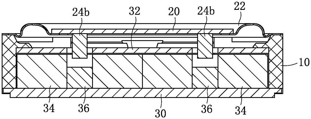
[0041] This embodiment is basically the same as Embodiment 1, the difference is that:

[0042] Such as image 3 As shown, the height of the driving magnet 24b is larger, and its lower surface exceeds the upper surface of the voice coil 34, that is, the lower end of the driving magnet 24b is inserted into the central hole of the voice coil 34, and there is a gap between the driving magnet 24b and the armature 36. vibration space.

Embodiment 3

[0044] This embodiment is basically the same as Embodiment 1, the difference is that:

[0045] Such as Figure 4 As shown, the size of the driving magnet 24c is consistent with the size of the center hole of the voice coil 34, or the size of the driving magnet 24c is larger than the size of the center hole of the voice coil 34, and the height of the driving magnet 24c is smaller than its width, which is a flat structure. In this embodiment, sufficient vibration space needs to be left between the driving magnet 24c and the magnetically permeable member 32 .

[0046] Such as Figure 5 Shown, the operating principle of the moving magnet loudspeaker of the present invention is as follows:

[0047] Taking the moving magnet loudspeaker described in Embodiment 1 as an example, the vibration direction of the diaphragm is the vertical direction. In the figure, ⊙ and ⊕ represent the direction of the current in the voice coil 34, and ⊙ represents the direction of the current perpendicu...


PUM


Abstract

The invention discloses a moving magnet type loudspeaker and relates to the technical field of electroacoustic products. The moving magnet type loudspeaker comprises a shell; a vibrating film and a voice coil parallel with the vibrating film are accommodated in the shell; a driving magnet is fixed on one side, near the voice coil, of the vibrating film; the voice coil forms an electromagnet after being electrified; and the voice coil and the driving magnet generate interaction force to drive the vibrating film to vibrate and generate sound. The moving magnet type loudspeaker solves the technical problem that the moving coil type loudspeaker is poor in high-frequency transient state response in the prior art. The moving magnet type loudspeaker provided by the invention is good in high-frequency transient state response, low in F0, high in sensitivity and high in integral performance, and can meet the performance requirement of high-fidelity equipment.

Description

technical field [0001] The invention relates to the technical field of electroacoustic products, in particular to a moving magnet loudspeaker. Background technique [0002] The loudspeaker is an important acoustic component of portable electronic equipment. It is used to complete the conversion between electrical signals and sound signals, and is an energy conversion device. At present, most of the speakers used in portable electronic devices are dynamic speakers. The working principle of the dynamic speaker is that the electrified voice coil is affected by the ampere force in the magnetic field, which drives the diaphragm to vibrate and produce sound. Due to its principle, the dynamic It is difficult to improve the high-frequency transient response of the conventional speaker, and the high-frequency performance is low, which cannot meet the performance requirements of current Hi-Fi (high-fidelity) equipment. Contents of the invention [0003] In view of the above defects...

Claims


Application Information

Patent Timeline
Patent Type & Authority Applications(China)
IPC IPC(8): H04R9/06H04R9/02
CPCH04R9/02H04R9/06H04R2400/11
Inventor 汲鹏程祖峰磊许超
Owner GOERTEK INC
Why Eureka
Try Eureka