Oil pump arrangement for a motor vehicle

A technology for motor vehicles and oil pumps, applied in transmission control, transmission parts, transmission boxes, etc., to achieve the effect of avoiding friction loss

Active Publication Date: 2017-08-29
VOLKSWAGEN AG
View PDF12 Cites 3 Cited by
  • Summary
  • Abstract
  • Description
  • Claims
  • Application Information

AI Technical Summary

Problems solved by technology

An additional oil pump mounted externally at the gearbox housing requires an additional interface which may have tightness issues
In addition, the device requires additional installation space outside the gearbox housing

Method used


Image

  • Oil pump arrangement for a motor vehicle
  • Oil pump arrangement for a motor vehicle
  • Oil pump arrangement for a motor vehicle

Examples


Embodiment Construction

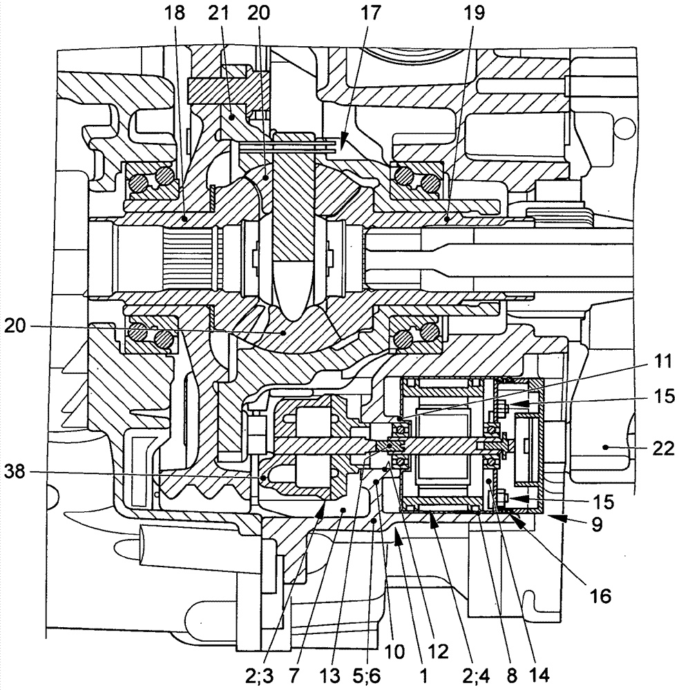
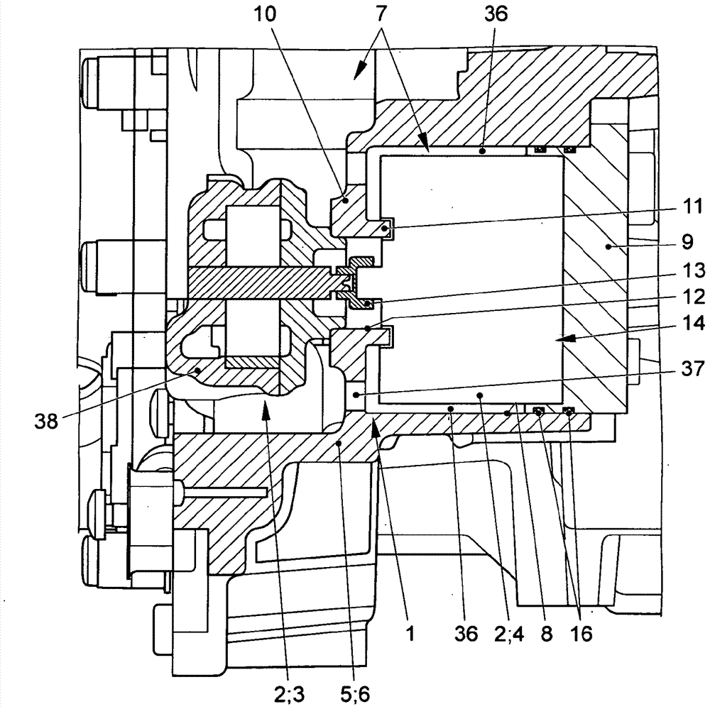
[0027] exist figure 1 and figure 2 An oil pump arrangement 1 with an additional oil pump 2 for a transmission (not shown in further detail) of a motor vehicle can be seen therein.

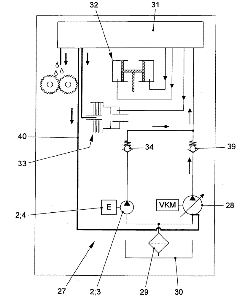
[0028] The additional oil pump 2 is integrated into the hydraulic circuit 26 or 27 (see Figure 4 Or 5), wherein the hydraulic circuits 26 , 27 each have a main oil pump 28 , wherein the main oil pump 28 is arranged parallel to the auxiliary oil pump 2 (with corresponding pump part 3 and pump motor 4 ). The pump part 3 is in particular designed as a gear pump. The pump part 3 can be designed as a gerotor pump, that is to say as a gear ring pump or also as a crescent gear pump.

[0029] Before discussing the hydraulic circuit further26,27, however, first one can base figure 1 and 2 Describe the arrangement and construction of the additional oil pump 2:

[0030] The auxiliary oil pump 2 has a hydrostatic pump part 3 and a pump motor 4 . The pump part 3 can be driven by the pump motor 4 and is...


PUM


Abstract

The invention relates to an oil pump arrangement (1) for a motor vehicle, comprising an oil pump (2) having a pump part (3) and an electric pump motor (4), wherein the pump part (3) is in operative connection with the pump motor (4), the pump part (3) and / or the pump motor (4) being mountable to a housing (5), the housing (5) partially delimiting an oil chamber (7). Tightness problems on the pump part (3) are prevented and the required installation space is low because the pump part (3) can be mounted within the housing (5) and the pump motor (4) can be mounted from the outside to the housing (5).

Description

technical field [0001] The invention relates to an oil pump arrangement for a motor vehicle with the features of claim 1 . Background technique [0002] An oil pump arrangement for a gearbox of a motor vehicle is known from DE 10 2007 018 504 A1. The hydraulic pump components and the electric pump motor form an oil pump in the form of a motor-pump unit. The motor-pump unit is arranged in the gearbox housing below the oil level in the oil sump. By means of the pump element, transmission oil is sucked in at the pump inlet and conveyed from the pump outlet into the lubricating line and in parallel into the cooling branch. Via the lubrication lines, the lubrication points of the gearbox are supplied with transmission oil. Via the cooling ducts, the working medium reaches one or more nozzles through which the transmission oil reaches the transmission components to be cooled. Immediately afterwards, transmission oil collects again in the transmission housing. In order to ensu...

Claims


Application Information

Patent Timeline
Patent Type & Authority Applications(China)
IPC IPC(8): F16H57/04F16H57/02F16H61/00
CPCF16H57/02F16H57/0441F16H61/0031F16H2057/02086
Inventor R.瓦尔内克W.克诺尔R.施普伦格H.塔格K.科内尔森T.比恩鲍姆F.米勒B.莫托尔斯特H.韦尔布鲁恩
Owner VOLKSWAGEN AG
Why Eureka
Try Eureka