Sewing machine

A technology for sewing machines and casings, which is applied to sewing machine components, sewing machine control devices, sewing equipment, etc., which can solve the problems of large structural changes, installation of reverse sewing drive and presser foot lift drive, complex structure, etc., and achieve improved transmission. The effect of improving efficiency, eliminating fit clearance, and simplifying transmission structure

Inactive Publication Date: 2017-10-13
JACK SEWING MASCH CO LTD
View PDF8 Cites 1 Cited by
  • Summary
  • Abstract
  • Description
  • Claims
  • Application Information

AI Technical Summary

Problems solved by technology

[0004] However, the structure of the automatic falling loose material in this technical solution is relatively complicated, and the structure is not compact enough when assembled with the automatic presser foot lifter structure, so that the reverse stitching driver and the presser foot lifter driver cannot be installed in the cavity of the casing at the same time. But its reverse sewing driver is installed in the housing cavity, but the presser foot lifter driver is installed on the base plate, so because the presser foot lifter driver is installed on the base plate, it is not beautiful enough and the structure is complicated, especially It cannot be well matched and compatible with the current mainstream built-in presser foot lifter structure, and it needs to make major changes to the current mainstream built-in presser foot lifter structure, resulting in large structural changes and high manufacturing costs

Method used


Image

  • Sewing machine
  • Sewing machine
  • Sewing machine

Examples


Embodiment Construction

[0023] The following are specific embodiments of the present invention and in conjunction with the accompanying drawings, the technical solutions of the present invention are further described, but the present invention is not limited to these embodiments.

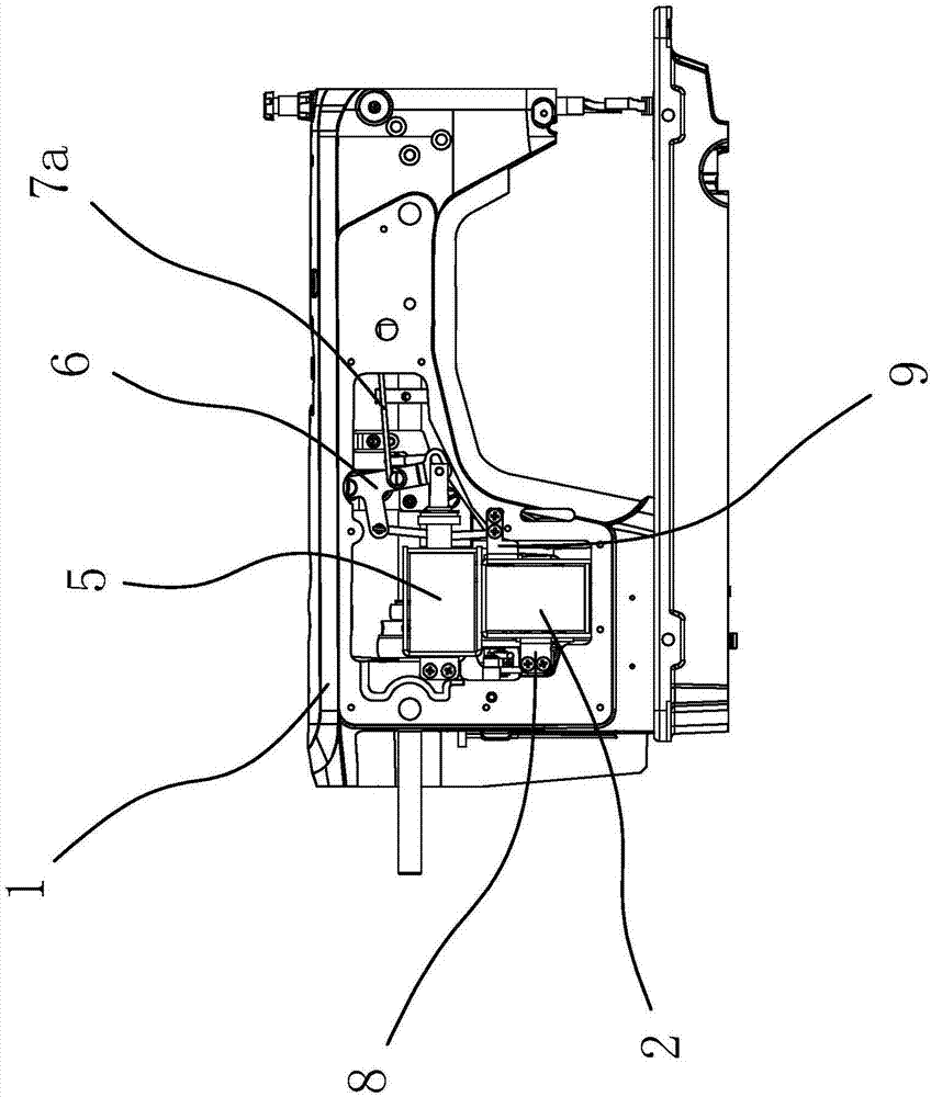
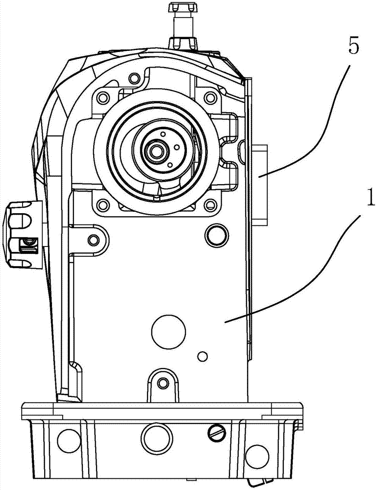
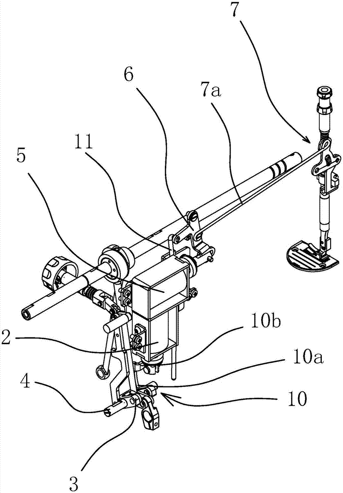
[0024] Such as Figure 1-4 Shown, this sewing machine comprises casing 1, automatic feeding mechanism and automatic presser foot lifting mechanism. The automatic reverse feeding mechanism includes a reverse feeding electromagnet 2 and a swing seat 3. The swing seat 3 is swingably connected to the casing 1 through a rotating shaft 4. The automatic presser foot lifting mechanism includes a presser foot lifting electromagnet 5, a presser foot lifting crank 6 and a lifter The presser foot lifting assembly 7 of the presser foot pull rod 7a, the reverse feeding electromagnet 2 and the presser foot lifting electromagnet 5 are all fixed in the casing 1 .

[0025] The reverse feed electromagnet 2 is vertically arranged and the iro...


PUM


Abstract

The invention provides a sewing machine and belongs to the technical field of machinery with an aim to solve the problem that a reverse-feed electromagnet and a presser-foot-lift electromagnet of an existing sewing machine cannot be built in simultaneously due to large space occupation. The sewing machine comprises a main case, the reverse-feed electromagnet, a swing seat, a reverse-seat pull rod, the presser-foot-lift electromagnet, a presser-foot-lift crank and a presser-foot-lift pull rod; the reverse-feed electromagnet is vertically arranged with the iron core facing downwards, the reverse-feed pull rod and a rotating shaft are vertically arranged with each other, two ends of the reverse-feed pull rod are hinged with the iron core of the reverse-feed electromagnet and the swing seat, the presser-foot-lift electromagnet is horizontally arranged with the iron core facing to the front end of the main case and is located above the reverse-feed electromagnet, the upper end of the presser-foot-lift crank is hinged to the main case while the lower end is hinged with the iron core of the presser-foot-lift electromagnet, and the presser-foot-lift pull rod is hinged to the middle portion of the presser-foot-lift crank. By the arrangement, matching compatibility with an original built-in type presser-foot-lift structure is achieved on the premise of trying not to change the structure of the built-in type presser-foot-lift structure, and the presser-foot-lift electromagnet and the reverse-feed electromagnet can be built in simultaneously through reasonable structural design.

Description

technical field [0001] The invention belongs to the technical field of machinery and relates to a sewing machine. Background technique [0002] A sewing machine is a machine that uses one or more sewing threads to form one or more stitches on the sewing material to interweave or sew one or more layers of sewing material. At present, sewing machines are widely used in the garment manufacturing industry, especially large-scale sewing machines used in factories, and are more widely used in production enterprises that manufacture garments in batches. [0003] In the existing sewing machines, the automatic reverse feeding structure includes a reverse feeding electromagnet, a swing seat and an automatic reverse feeding rod group. The reciprocating motion of the reverse feeding electromagnet drives the automatic reverse feeding rod group to move and then controls the swing of the swing seat, and finally realizes Automatic reverse sewing function. In the actual sewing machine stru...

Claims


Application Information

Patent Timeline
Patent Type & Authority Applications(China)
IPC IPC(8): D05B27/00D05B29/02D05B69/18
CPCD05B27/00D05B29/02D05B69/18
Inventor 何明金祝书伟陈文双
Owner JACK SEWING MASCH CO LTD
Why Eureka
Try Eureka