Refuse landfill film laying machine

A landfill and film laying machine technology, applied in the direction of spreading thin soft materials, thin material processing, transportation and packaging, etc., can solve problems such as low efficiency, harsh on-site environment, environmental protection requirements and unreachable production capacity, etc. Achieve the effect of convenient placement and welding

Active Publication Date: 2017-10-17
扬州铭德环境科技有限公司
View PDF7 Cites 1 Cited by
  • Summary
  • Abstract
  • Description
  • Claims
  • Application Information

AI Technical Summary

Problems solved by technology

[0002] The existing landfill adopts artificial film laying, which is completely dependent on manual work. Due to the weather, the site environment is harsh, the efficiency is extremely low, and the environmental protection requirements and production capacity cannot be met.

Method used


Image

  • Refuse landfill film laying machine
  • Refuse landfill film laying machine
  • Refuse landfill film laying machine

Examples


Embodiment Construction

[0030] The present invention will be further described below in conjunction with accompanying drawing:

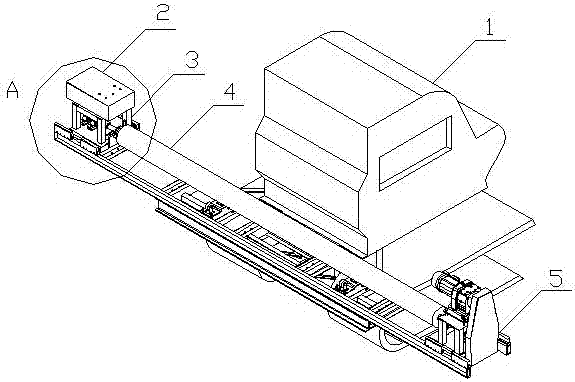
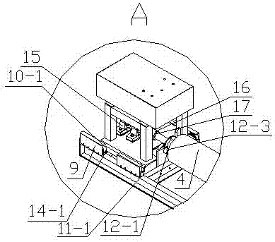
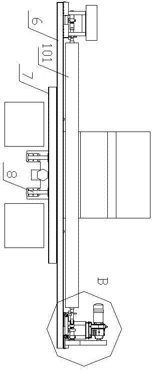
[0031] A film spreading machine for a landfill site, comprising a base vertical support 8 fixed to a bulldozer 1, a base cross support 7 is fixed on the base vertical support 8, a fixed support 6 is fixed on the upper part of the base cross support 7, and the fixed support 6 The first main shaft support frame 12-1 and the second main shaft support frame 12-2 are fixed on both sides of the upper part; the first main shaft support frame 12-1 and the second main shaft support frame 12-2 support the main shaft 4, and the main shaft 4 Both ends are supported on the first main shaft support frame 12-1 and the second main shaft support frame 12-2, the main shaft 4 is wound with a film 101, the main shaft 4 can be mounted on the first main shaft support frame 12-1, the second main shaft support frame 12-2 up spin.

[0032] The first slide rail 14-1 is set on the top of the fixed b...


PUM


Abstract

The invention relates a refuse landfill film laying machine. The refuse landfill laying machine comprises a base vertical supporting piece fixed to a bulldozer, the base vertical supporting piece is fixedly provided with a base transverse supporting piece, a fixed support is fixedly arranged at the upper portion of the base transverse supporting piece, and a first main shaft supporting frame and a second main shaft supporting frame are fixedly arranged at the two sides of the upper portion of the fixed support; main shafts are supported on the first main shaft supporting frame and the second main shaft supporting frame, the two ends of each main shaft are supported on each of the first main shaft supporting frame and the second main shaft supporting frame, thin film is twined on the main shafts, and the main shafts can rotate on the first main shaft supporting frame and the second main shaft supporting frame. The refuse landfill film laying machine is reasonable in structure, convenient to use and advanced and scientific in method, through the refuse landfill film laying machine, manual film laying is replaced, by making a motor control the speed through variable frequencies, making a left probe and a right probe conduct control and making a left slide rail and a right slide rail manually pushed to place the rolled film, film rolling equipment is attached to an on-site bulldozer, and garbage is effectively covered with the rolled film.

Description

technical field [0001] The invention relates to a film-laying machine for a landfill site, and belongs to the technical field of film-laying machine design. Background technique [0002] The existing landfill adopts artificial film laying, which is completely dependent on labor. Due to the weather, the site environment is harsh, the efficiency is extremely low, and the environmental protection requirements and production capacity cannot be met. Therefore, people are in urgent need of an artificial intelligence film-laying device that can reduce labor and facilitate the film-laying of landfills. Contents of the invention [0003] The object of the present invention is to aim at the deficiencies of the above-mentioned prior art, and provide an artificial intelligence film-laying device with reasonable structure, convenient use, reduced labor, and convenient film-laying on landfills. [0004] The object of the present invention is achieved in this way, a film spreading machi...

Claims


Application Information

Patent Timeline
IPC IPC(8): B65H47/00
CPCB65H47/00B65H2701/19Y02W30/30
Inventor 喻俊波张胜兵
Owner 扬州铭德环境科技有限公司
Why Eureka
Try Eureka