High-speed optical delay linear scanning device

A linear scanning and optical technology, applied in the field of optical detection, can solve the problems of large drag coefficient and difficulty in further increasing the delay scanning rate, and achieve the effect of small drag coefficient, good stability and high scanning rate

Pending Publication Date: 2017-11-24
HUAZHONG PHOTOELECTRIC TECH INST (CHINA SHIPBUILDING IND CORP THE NO 717 INST)
View PDF4 Cites 10 Cited by
  • Summary
  • Abstract
  • Description
  • Claims
  • Application Information

AI Technical Summary

Problems solved by technology

However, due to the design characteristics of the structure and shape of the planar mirror array, the drag coefficient when it rotates is relatively large, and it is difficult to further increase the delay scanning rate under the premise of ensuring stability.

Method used


Image

  • High-speed optical delay linear scanning device
  • High-speed optical delay linear scanning device

Examples


Embodiment Construction

[0021] The present invention will be described in further detail below in conjunction with the accompanying drawings and embodiments.

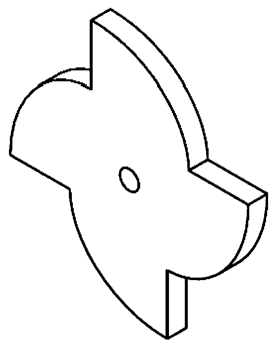
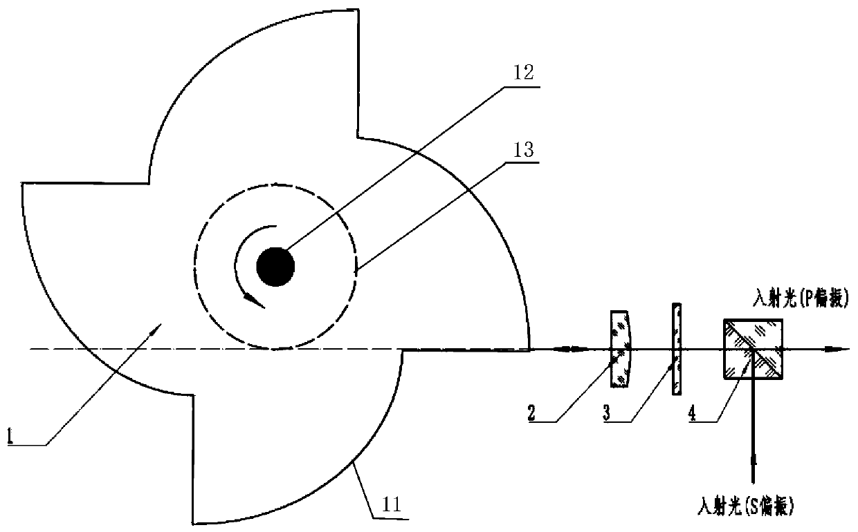
[0022] refer to figure 1 , figure 2 As shown, as the first embodiment of the present invention, a new high-speed, stable, linear, continuous optical delay scanning device is disclosed. A wave plate 3, a cubic polarizing beam splitter 4, and a motor are formed. The center of the fan-blade reflector 1 is provided with a rotating hole 12, which is used to connect to the drive shaft of the motor and rotate counterclockwise at a constant speed around the central axis. The fan blade The type reflector 1 is composed of multiple (≥2) identical fan blade reflection surfaces 11 and a base circle 13 coaxial with the center of the fan blade reflection surface 11. The fan blade reflection surface 11 conforms to the circular involute equation, and adopts The outer curved surface of the involute is used as an optical fan blade reflective surface, and the...


PUM


Abstract

The invention discloses a high-speed optical delay linear scanning device, which comprises a fan-blade-shaped reflector, a quarter-wave plate, a polarizing beam splitter and a motor. The fan-blade-shaped reflector is formed by a plurality of same fan-blade-shaped reflection planes and a base circle coaxially with the centers of the fan-blade-shaped reflection planes. Each fan-blade-shaped reflection plane adopts an outer curved surface of a base circle involute; the plurality of fan-blade-shaped reflection planes are in uniform-angle distribution in the circumference of the base circle. A cylindrical mirror, the quarter-wave plate and the polarizing beam splitter are arranged in sequence, and the direction of optical axis thereof is overlapped with the tangent line of the base circle; and when incident to the polarizing beam splitter, S-polarization incident light is refracted thereby first, then, passes through the quarter-wave plate and the cylindrical mirror in sequence, is incident to the outer surface of the fan-blade-shaped reflector, then, is reflected back in the same way, and then, passes through the cylindrical mirror, the quarter-wave plate and the polarizing beam splitter in sequence to form P-polarized emergent light.

Description

technical field [0001] The invention belongs to the technical field of optical detection, and in particular relates to a high-speed optical time-delay linear scanning device. Background technique [0002] The optical delay scanning device is used to realize the delay scanning function between two beams of light, and is widely used in optical detection systems based on ultrafast time resolution, such as optical coherence tomography and terahertz time-domain spectroscopy. [0003] The early optical time-delay device used the reciprocating linear motion of the mirror to realize the time-delay scanning, and the scanning rate could only reach the order of 10 Hz. In order to increase the scanning rate, optical time-lapse scanning mechanisms using rotary motion have been widely reported. Among them, the time-lapse scanning technology using the involute mirror as the key component is a research hotspot in recent years. [0004] In 2004, Xu Jingzhou and others reported a time-lapse...

Claims


Application Information

Patent Timeline
Patent Type & Authority Applications(China)
IPC IPC(8): G02B26/10G02B26/12
CPCG02B26/105G02B26/12
Inventor 袁英豪姚远洪普李长庚莫时骏
Owner HUAZHONG PHOTOELECTRIC TECH INST (CHINA SHIPBUILDING IND CORP THE NO 717 INST)
Why Eureka
Try Eureka