Pipe burying pay-off device for water conservancy construction and with length recording function

A technology of recording function and pay-off device, which is applied in the field of buried pipe pay-off device with built-in length recording function for water conservancy construction. The effect of long service life and simple structure

Inactive Publication Date: 2017-12-22
沈利丹
View PDF0 Cites 9 Cited by
  • Summary
  • Abstract
  • Description
  • Claims
  • Application Information

AI Technical Summary

Problems solved by technology

[0003] In the process of water conservancy construction, the cables will be inserted into the buried pipes. During the laying and insertion of the cables, due to the inability to control the laying speed of the cables, it is easy to cause the cables to be blocked in the pipes. This requires the operator to Pulling out the cables and re-laying them not only leads to low efficiency, but also wastes a lot of physical strength of the operators. The existing buried pipe release devices often use extrusion and clamping when fixing the cables. It will cause damage to the cable skin and affect the service life of the cable, and it is not easy to measure the length of the cable during the laying of the cable, which will affect the work progress. At the same time, there is no tool box for placing tools on the buried pipe release device. When the equipment is damaged, it will affect the progress of the wire setting work and affect the work efficiency

Method used


Image

  • Pipe burying pay-off device for water conservancy construction and with length recording function
  • Pipe burying pay-off device for water conservancy construction and with length recording function
  • Pipe burying pay-off device for water conservancy construction and with length recording function

Examples


Embodiment Construction

[0020] The technical solution of this patent will be further described in detail below in conjunction with specific embodiments.

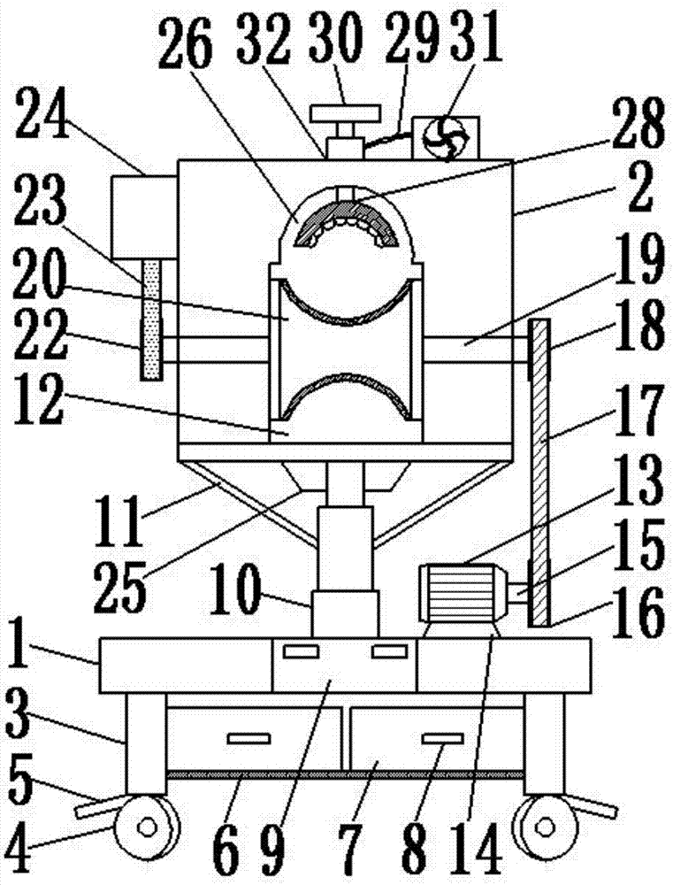
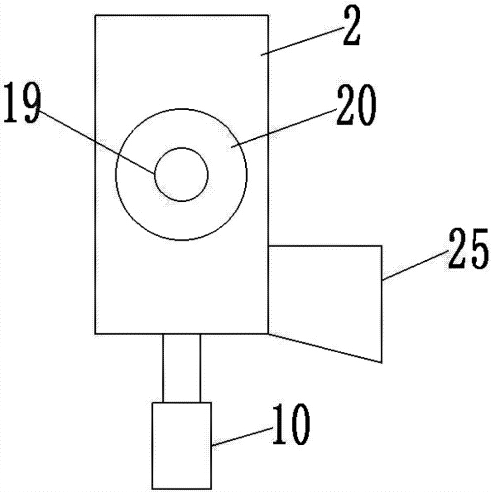
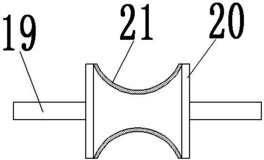
[0021] see Figure 1-4 , a buried pipe pay-off device with its own length recording function for water conservancy construction, comprising a support base 1 and a wire release box 2; the lower end of the support base 1 is connected with a support leg 3; the support leg 3 is provided with four , symmetrically distributed around the lower end of the support seat 1; the bottom end of the support leg 3 is provided with a walking wheel 4; A support plate 6 is provided; a tool box 7 is provided on the support plate 6 to place various tools; a handle 8 is provided on the tool box 7 to facilitate the opening of the tool box 7; the upper end of the support seat 1 is set in the center There is a hydraulic lifting column 10; the hydraulic lifting column 10 is driven by a hydraulic power box 9; the hydraulic power box 9 is arranged in the support seat 1; the ...


PUM


Abstract

The invention discloses a pipe burying pay-off device for water conservancy construction and with a length recording function. The pipe burying pay-off device for water conservancy construction and with the length recording function comprises a supporting base and a pay-off box; the lower end of the supporting base is connected with supporting legs; walking wheels are arranged at the bottom ends of the supporting legs; a hydraulic lifting column is arranged in the right middle of the upper end of the supporting base; the top end of the hydraulic lifting column is connected to the bottom end of the pay-off box; a through groove is formed in the pay-off box; a pay-off roller is arranged in the through groove; a rotating shaft is arranged in the pay-off roller; a transmission wheel is arranged on a right side suspension arm of the rotating shaft; the transmission wheel is connected to a driving wheel through a belt; a rotating wheel is hung on a left side suspension arm of the rotating shaft; the rotating wheel is connected to a distance measuring box through a transmission belt; a sleeve is fixedly arranged in the right middle of the top end of the pay-off box; a hollow pipe is connected in the sleeve in a sliding manner; and the bottom end of the hollow pipe is connected with a pressing and holding plate. The pipe burying pay-off device for water conservancy construction and with the length recording function is simple in structure and convenient to use, and due to the arrangement of the distance measuring box, a cable laying speed during construction can be controlled.

Description

technical field [0001] The invention relates to the technical field of water conservancy construction equipment, in particular to a buried pipe setting-off device with a length recording function for water conservancy construction. Background technique [0002] Water conservancy project is a basic industry and important facility for the development of a country and society. It plays a very important role in ensuring people's life and production. Creator is an essential process for the creation of water conservancy benefits. In the process of water conservancy construction, it is often necessary to set out and pull buried pipes to facilitate the laying of pipelines. [0003] In the process of water conservancy construction, the cables will be inserted into the buried pipes. During the laying and insertion of the cables, due to the inability to control the laying speed of the cables, it is easy to cause the cables to be blocked in the pipes. This requires the operator to Pull...

Claims


Application Information

Patent Timeline
Patent Type & Authority Applications(China)
IPC IPC(8): B65H61/00B65H75/26B65H59/04B65H49/00B65H49/18B65H49/32H02G1/08B08B1/02B08B1/00
CPCH02G1/08B65H49/00B65H49/18B65H49/32B65H59/04B65H61/00B65H75/26B08B1/006B08B1/02B65H2402/40B65H2701/34B65H2402/20
Inventor 沈利丹沈佳佳
Owner 沈利丹
Why Eureka
Try Eureka