Circular cutting blade with accurate positioning structure and cutting tool

A cutting blade, accurate positioning technology, applied in the field of cutting processing, can solve the problems of cutting vibration, lack of concentricity, deformation of fasteners, etc., and achieve the effect of improving clamping rigidity

Active Publication Date: 2018-01-05
ZHUZHOU CEMENTED CARBIDE CUTTING TOOLS CO LTD
View PDF6 Cites 4 Cited by
  • Summary
  • Abstract
  • Description
  • Claims
  • Application Information

AI Technical Summary

Problems solved by technology

[0003] Although the round blade has the above advantages when it is clamped and cut through the center hole, the center of the fastener and the center axis of the round blade are not concentric. When clamping, only a small area of ​​contact with the center hole of the round bla...

Method used


Image

  • Circular cutting blade with accurate positioning structure and cutting tool
  • Circular cutting blade with accurate positioning structure and cutting tool
  • Circular cutting blade with accurate positioning structure and cutting tool

Examples


Embodiment 1

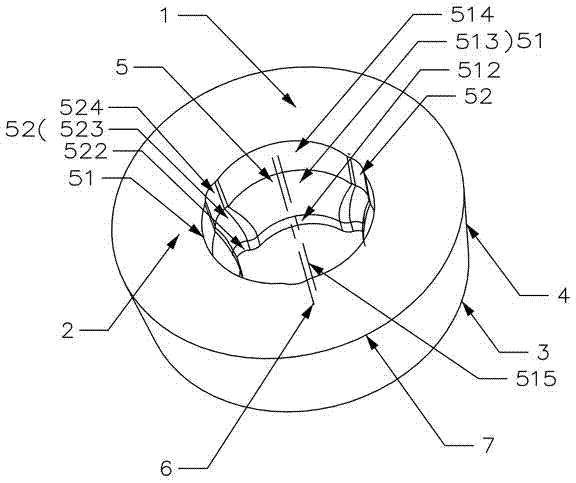
[0035] Such as Figures 1 to 4 As shown, the circular cutting insert with an accurate positioning structure in this embodiment includes a circular blade body 1 composed of an upper surface 2, a lower surface 3, and a side surface 4 connecting the upper surface 2 and the lower surface 3. The blade body 1 There is a central hole 5 that runs through the upper surface 2 and the lower surface 3. The blade body 1 is symmetrical about the central axis 6 of the central hole 5. The upper surface 2 intersects with the side 4 to form a cutting edge 7. The inner surface of the central hole 5 is provided with at least one There is an arc-shaped groove 51 that can cooperate with the surface of the fastening screw 11 for fixing the circular cutting blade.

[0036]In this embodiment, the inner surface of the center hole 5 is provided with three arc-shaped grooves 51, and the three arc-shaped grooves 51 are evenly arranged along the inner surface of the center hole 5, and the three arc-shaped ...

Embodiment 2

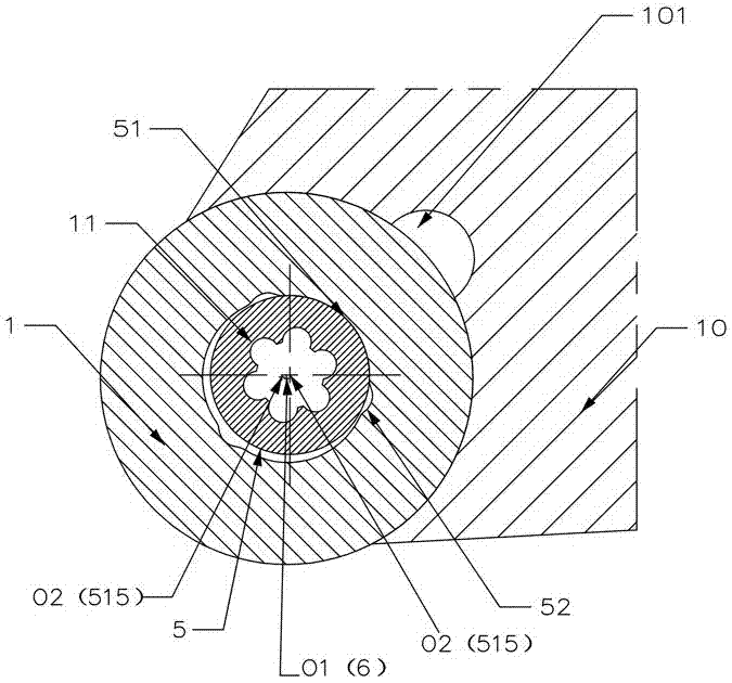
[0045] Such as Figure 5 As shown, the cutting tool of this embodiment includes a cutter body 10 and a fastening screw 11, the cutter body 10 is a square cutter bar, and a cutter groove 101 is provided on the cutter body 10, and the cutting tool also includes a circle in embodiment 1. Shaped cutting blades, the number of circular cutting blades corresponds to the number of sipe grooves 101, and the present embodiment is set to one. The circular cutting blade is installed in the sipe 101 , and the fastening screw 11 is passed through the central hole 5 , concentrically contacts with at least one arc-shaped groove 51 and presses the circular cutting blade into the sipe 101 .

[0046] In this embodiment, the positioning and installation process of the circular cutting insert is as described in Embodiment 1. In this embodiment, in the final positioning, the arc-shaped groove 51 and the fastening screw 11 form three sets of continuous arc-shaped over-positioning clamping.

[0047...

Embodiment 3

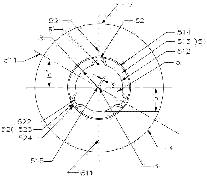
[0051] Such as Figures 6 to 8 As shown, the circular cutting insert of this embodiment is basically the same as that of Embodiment 1, the difference is that:

[0052] In this embodiment, there are four arc-shaped grooves 51, four corner grooves 52, and each corner groove 52 is arranged between two adjacent arc-shaped grooves 51. Among the arc-shaped grooves 51 , two of them are symmetrical about the central axis 6 , and the other two are also symmetrical about the central axis 6 . Similarly, the four corner grooves 52 also have the same symmetrical structure.

[0053] In this embodiment, the center-to-center distance between two arc-shaped grooves 51 (located on the same straight line) that are symmetrical about the center of the central axis 6 is 2S.

[0054] In this embodiment, the groove symmetry plane 511 and the corner groove symmetry plane 521 are perpendicular to each other.

[0055] In this embodiment, the positioning and installation process of the circular cutting...


PUM


Abstract

The invention discloses a circular cutting blade with an accurate positioning structure and a cutting tool. The circular cutting blade comprises a circular blade body which consists of an upper surface, a lower surface and side surfaces connecting the upper surface to the lower surface, wherein a central hole which penetrates through the upper surface and the lower surface is formed in the blade body; the blade body is centrosymmetric with respect to a central axis of the central hole; the upper surface is crossed with the side surfaces to form cutting edges; at least one circular-arc-shaped groove which is matched with the surface of a fastening screw for fixing the circular cutting blade is formed in the inner surface of the central hole; and offset distance is formed between the groovecentral axis of the circular-arc-shaped groove and the central axis. The cutting tool adopts the cutting blade. The circular cutting blade has the advantages of being reliable and stable in positioning, prolonging the service life of the cutting blade and being capable of preventing the circular blade from rotating in the peripheral direction.

Description

technical field [0001] The invention relates to cutting processing technology, in particular to a circular cutting blade and a cutting tool with an accurate positioning structure. Background technique [0002] During the cutting process of the blade, the clamping strength and rigidity of the circular blade have a great influence on the cutting ability of the circular blade, and the clamping stability of the cutting slice especially has a substantial impact on the cutting efficiency and cutting accuracy of the circular blade. The circular blade with stable clamping not only has high cutting efficiency, precision but also has a long life. The vibration of the circular blade with unstable clamping is easy to produce during cutting, which will cause the rapid wear or even collapse of the circular blade, which greatly shortens the life of the circular blade. . In order to improve the cutting performance of round blades in the industry, round blades are designed into a variety of...

Claims


Application Information

Patent Timeline
IPC IPC(8): B23B27/00B23B27/16
Inventor 江爱胜王社权刘敏
Owner ZHUZHOU CEMENTED CARBIDE CUTTING TOOLS CO LTD
Why Eureka
Try Eureka