Buried structure of ground hook lock

A technology of buried structure and ground hook lock, which is applied in the field of locks, can solve the problems of low installation efficiency and time-consuming, etc., and achieve the effect of improving installation efficiency, improving bearing capacity and ensuring safety

Active Publication Date: 2018-02-09
FUJIAN ANLIN INTELLIGENT SCI & TECH
View PDF5 Cites 0 Cited by
  • Summary
  • Abstract
  • Description
  • Claims
  • Application Information

AI Technical Summary

Problems solved by technology

Due to the strict requirements for the cooperation between the lock head and the ground lock, it will take a lot of time to adjust the position and angle of the buried box during the installation of the buried box, and the installation efficiency is low

Method used


Image

  • Buried structure of ground hook lock
  • Buried structure of ground hook lock

Examples


Embodiment Construction

[0030] The present invention will be further described below in conjunction with the embodiments in the accompanying drawings.

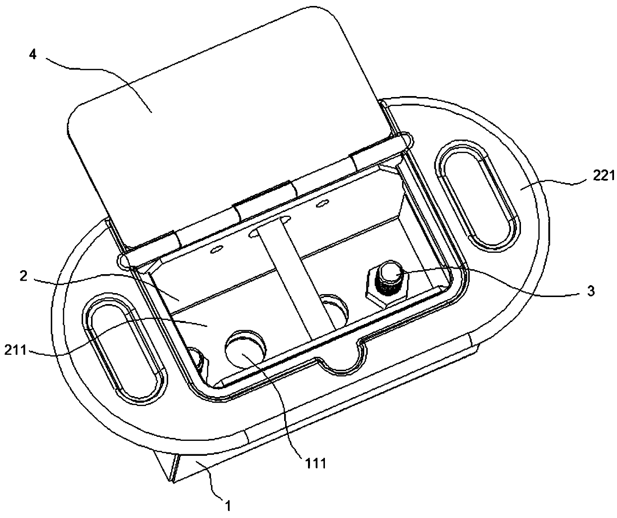
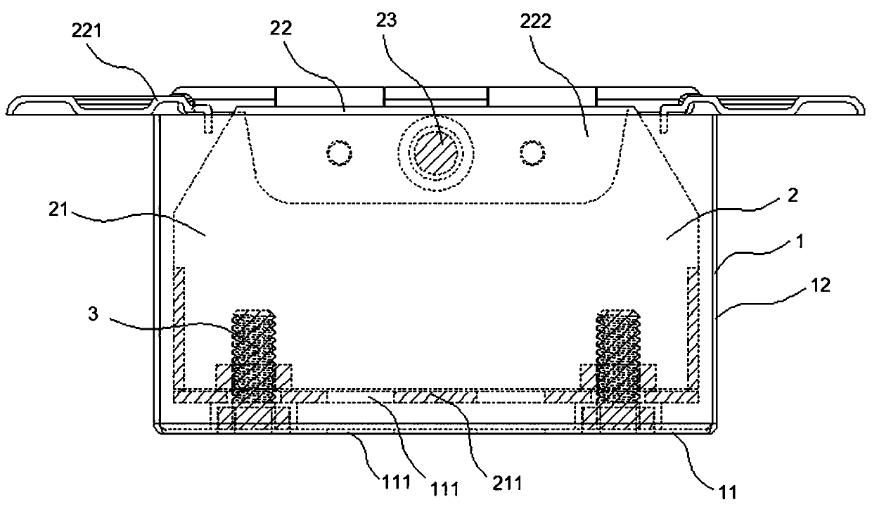
[0031] Such as figure 1 and figure 2 As shown, the buried structure includes an embedded box 1. The embedded box 1 includes a fixing part 11 and a support part 12 surrounding the fixing part 11. The fixing part 11 and the supporting part 12 form a cavity with an open end; the ground hook box 2, It includes a box body 21 located in the cavity, a cover plate 22 located outside the cavity, and a limit rod 23. The cover plate 22 is provided with an opening relative to the limit rod 23. The box body 21 includes a bottom plate 211 opposite to the fixed part 11; the bottom plate A screw 3 is connected between 211 and the fixing part 11 , and the fixing part 11 is provided with an expansion screw hole 111 . The side of the cover plate 22 is in contact with the open end of the embedded box 1 or the ground, and one end of the box body 21 is connected with t...


PUM


Abstract

The invention provides a buried structure of a ground hook lock. The buried structure comprises a pre-embedded box and a ground hook box, wherein the pre-embedded box comprises a fixing part and a supporting part surrounding the fixing part, and the fixing part and the supporting part form a cavity provided with an opening at one end; the ground hook box comprises a box body located in the cavity,a cover plate located on the outer side of the cavity and a limiting rod; an opening is formed in the cover plate opposite to the limiting rod, and the box body comprises a bottom plate which is opposite to the fixing part; and a screw is connected between the bottom plate and the fixing part, and the fixing part is provided with an expansion screw hole.

Description

technical field [0001] The invention relates to the technical field of locks, in particular to a ground hook lock buried structure. Background technique [0002] The ground hook lock used by the rolling door is mainly locked by engaging with the ground hook located on the ground or on the door frame. The lock head moves with the door body. When closing the rolling shutter door, the lock head is close to the ground lock buried under the ground. The limit post is blocked to limit the movement of the rolling shutter door. The current buried structure is a buried box and a decorative plate on the upper end, the buried box is fixed under the ground, and the limit column is fixed in the buried box. Due to the strict requirements for the cooperation between the lock head and the ground lock, it will take a lot of time to adjust the position and angle of the buried box during the installation of the buried box, and the installation efficiency is low. Contents of the invention ...

Claims


Application Information

Patent Timeline
Patent Type & Authority Applications(China)
IPC IPC(8): E06B9/80E05B65/00
CPCE05B65/00E06B9/80E06B2009/801
Inventor 高秋波
Owner FUJIAN ANLIN INTELLIGENT SCI & TECH
Why Eureka
Try Eureka