Convenient electric power supply mechanism

An electric power supply and convenient technology, which is applied in the direction of circuits, electrical components, and parts of connecting devices, etc., can solve problems such as the difficulty of manually pulling out the power supply head, endangering the personal safety of the equipment, and instability

Inactive Publication Date: 2018-02-16
朱亚伟
View PDF2 Cites 2 Cited by
  • Summary
  • Abstract
  • Description
  • Claims
  • Application Information

AI Technical Summary

Problems solved by technology

This tends to require a high pull-out force when pulling the power supply head out of the power supply hole; therefore, it makes it difficult to pull out the power supply head manually
Moreover, when pulling out manually, due to the instability of the force, it is easy to cause sparks with the electrical contacts during the process of pulling out the power supply head, endangering the safety of equipment and personal, and it is difficult to ensure the reliability and stability of the electrical connection

Method used


Image

  • Convenient electric power supply mechanism
  • Convenient electric power supply mechanism
  • Convenient electric power supply mechanism

Examples


Embodiment Construction

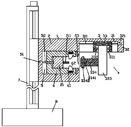
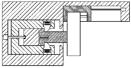
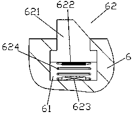
[0016] Such as Figure 1-Figure 6 As shown, a convenient electric power supply mechanism of the present invention includes a casing 1 composed of a power supply part 2 and a plug-in part 3 and a lifting device 7 arranged on the left side of the casing 1. The inside of the power supply part 2 An activity cavity 5 is provided, and the center position of the activity cavity 5 is provided with a power supply block 21 whose front and rear ends are fixedly connected with the power supply part 2, and a power supply pin 211 is provided on the right side of the power supply block 21, and the power supply block 21 21 is slidably connected with a U-shaped moving part 6 on the outside, and the U-shaped moving part 6 is provided with a first screw rod 52 threaded and connected, and the first screw rod 52 is extended to both sides, and the U-shaped moving part 6 right The two sets of support arms on the side are symmetrically provided with clamping slide chambers 61, and the opposite sides ...


PUM


Abstract

The invention discloses a convenient electric power supply mechanism, which comprises a housing composed of a power supply part and a plug-in part, and a lifting device arranged on the left side of the housing. A movable cavity is arranged inside the power supply part. The center of the cavity is provided with a power supply block whose front and rear ends are fixedly connected to the power supply part, and a power supply pin is provided on the right side of the power supply block, and a U-shaped moving part is slidably connected to the outer side of the power supply block, and the U-shaped moving part The part is provided with the first screw rod that is threaded and connected, and the first screw rod is extended to both sides. The two sets of arms on the right side of the U-shaped moving part are symmetrically provided with a locking sliding cavity. A clamping assembly is provided on the opposite side of the clamping sliding chamber, and a funnel-shaped opening communicating with the movable chamber is provided on the inner wall of the power supply part on the right side of the movable chamber; the invention has a simple structure and can realize automatic plugging and unplugging. High safety, high reliability and stability of plug-in engagement.

Description

technical field [0001] The invention relates to the field of electric power supply, in particular to a convenient electric power supply mechanism. Background technique [0002] When the power supply head of the power supply device is in contact with the power supply hole, in order to ensure good electrical contact and have a stable holding force, the joint between the power supply head and the power supply hole usually has a strong joint force or friction force. This often requires a greater pull-out force when the power supply head is pulled out from the power supply hole; therefore, it brings difficulties to manually pull out the power supply head. Moreover, when pulling out manually, due to the instability of the force, it is easy to cause sparks with the electrical contacts during the process of pulling out the power supply head, endangering the safety of equipment and personal, and it is difficult to ensure the reliability and stability of the electrical connection . ...

Claims


Application Information

Patent Timeline
Patent Type & Authority Applications(China)
IPC IPC(8): H01R13/627H01R13/629
CPCH01R13/629H01R13/627
Inventor 朱亚伟
Owner 朱亚伟
Why Eureka
Try Eureka