Electric braking electromechanical drive architecture for aircraft and braking force control method

A technology of braking control and drive control, applied in aircraft braking arrangements, control mechanisms, brakes, etc., can solve problems such as the deterioration of the force condition of the landing gear, the reduction of aircraft braking ability, and the loss of braking ability, so as to shorten the braking distance, prevent the The effect of deviating from the runway and improving safety

Active Publication Date: 2018-02-23
XIAN AVIATION BRAKE TECH
View PDF8 Cites 5 Cited by
  • Summary
  • Abstract
  • Description
  • Claims
  • Application Information

AI Technical Summary

Problems solved by technology

[0006] In order to overcome the failure state of the drive control channel of the electromechanical actuator in the prior art, the electromechanical actuators on some wheel brake devices will completely lose their braking ability, resulting in a reduction in the braking ability of the aircraft, or the brake will run away. This invention proposes an aircraft electric brake electromechanical drive structure and a braking force control method.

Method used


Image

  • Electric braking electromechanical drive architecture for aircraft and braking force control method
  • Electric braking electromechanical drive architecture for aircraft and braking force control method
  • Electric braking electromechanical drive architecture for aircraft and braking force control method

Examples


Embodiment 1

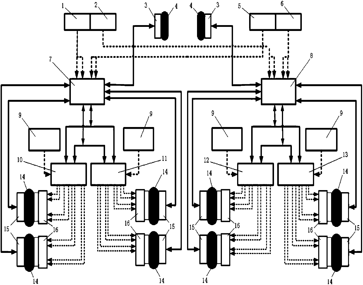
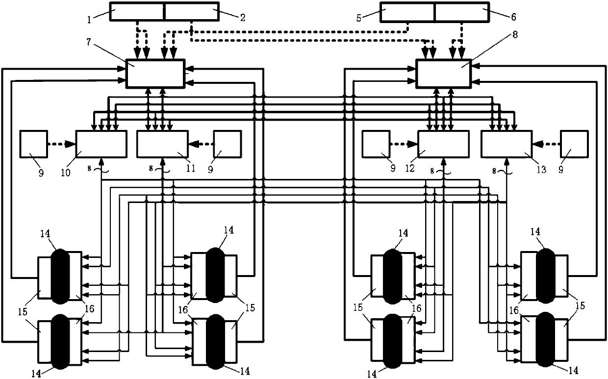
[0043] In this embodiment, an aircraft with eight main wheels is used as the target aircraft, and a typical aircraft electric brake control and monitoring system is constructed, such as figure 2 As shown, multiple electromechanical actuators on each main brake wheel are controlled by different electromechanical drivers. On this basis, the aircraft electric brake electromechanical drive architecture and braking force control method of the present invention are introduced. In order to have a uniform brake pressing force between the brake disc and the static disc, to ensure the stability of the braking torque and the uniform wear of the disc surface, four electromechanical actuators are evenly distributed in the circumferential direction of the end face of the main brake wheel brake device. Universal applicability.

[0044] This embodiment includes a command control framework and a drive control framework.

[0045]The command control architecture includes the captain left brake...

Embodiment 2

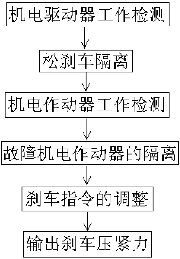
[0055] This embodiment is a braking force control method for the electromechanical drive framework of the aircraft electric brake according to the present invention when the electric brake power supply unit, the electromechanical driver and the electromechanical actuator fail. The specific process is:


PUM


Abstract

The invention discloses an electric braking electromechanical drive architecture for an aircraft and a braking force control method. Each electromechanical driver in a driving control architecture isrespectively connected with an electromechanical actuator on each machine wheel brake apparatus, and simultaneously receives a left machine wheel braking integrated instruction and a right machine wheel braking integrated instruction from a first braking control and monitoring unit and a second braking control and monitoring unit. Each main wheel remote data concentrator mounted on each undercarriage wheel axle transfers the generated signal to the first braking control and monitoring unit or the second braking control and monitoring unit on the same side of the aircraft. According to the electric braking electromechanical drive architecture disclosed by the invention, the performance of a braking system can be ensured to the greatest degree in a multi-failure state of the aircraft, the drive architecture has extremely high safety, respectively and independently controlled redundancy advantages of multiple electromechanical actuators in the braking system are fully achieved, failure isolation and redundancy management abilities of the aircraft electromechanical braking system and the system reconstruction capability in a failure state are improved, the fault tolerance and mission reliability are enhanced, and the aircraft braking safety is ensured.

Description

technical field [0001] The invention belongs to the field of electromechanical actuator control in aircraft brake system engineering, and in particular relates to the improvement of the electromechanical drive structure of aircraft electric brakes. Background technique [0002] Boeing's B787 aircraft is currently the most advanced electric brake system, using electromechanical actuation and drive control technology. figure 1 It is the structural principle diagram of the brake control and monitoring system of B787 aircraft, mainly including one captain left brake command sensor 1 and one captain right brake command sensor 2, two front wheel remote data concentrators 3 and two front wheel 4, One chief pilot left brake command sensor 5 and one chief pilot right brake command sensor 6, one first brake control and monitoring unit 7 and one second brake control and monitoring unit 8, four electric brake power units 9, the first electromechanical driver 10. One each of the second ...

Claims


Application Information

Patent Timeline
Patent Type & Authority Applications(China)
IPC IPC(8): B64C25/44B60T13/74B60T8/17B60T8/88
CPCB60T8/1703B60T8/885B60T13/74B60T2270/40B64C25/44
Inventor 张谦张颖姝
Owner XIAN AVIATION BRAKE TECH
Why Eureka
Try Eureka