

Wind power generating device
A technology of wind power generation device and generator, which is applied in wind power generators, wind power motor combinations, wind power generators at right angles to the wind direction, etc. It can solve the problems of low wind capture efficiency, inconvenient maintenance, poor wind resistance, etc., and achieve convenient movement , Easy to wire out, easy to install
- Summary
- Abstract
- Description
- Claims
- Application Information
AI Technical Summary
Problems solved by technology
Method used
Image

Examples
Embodiment 1
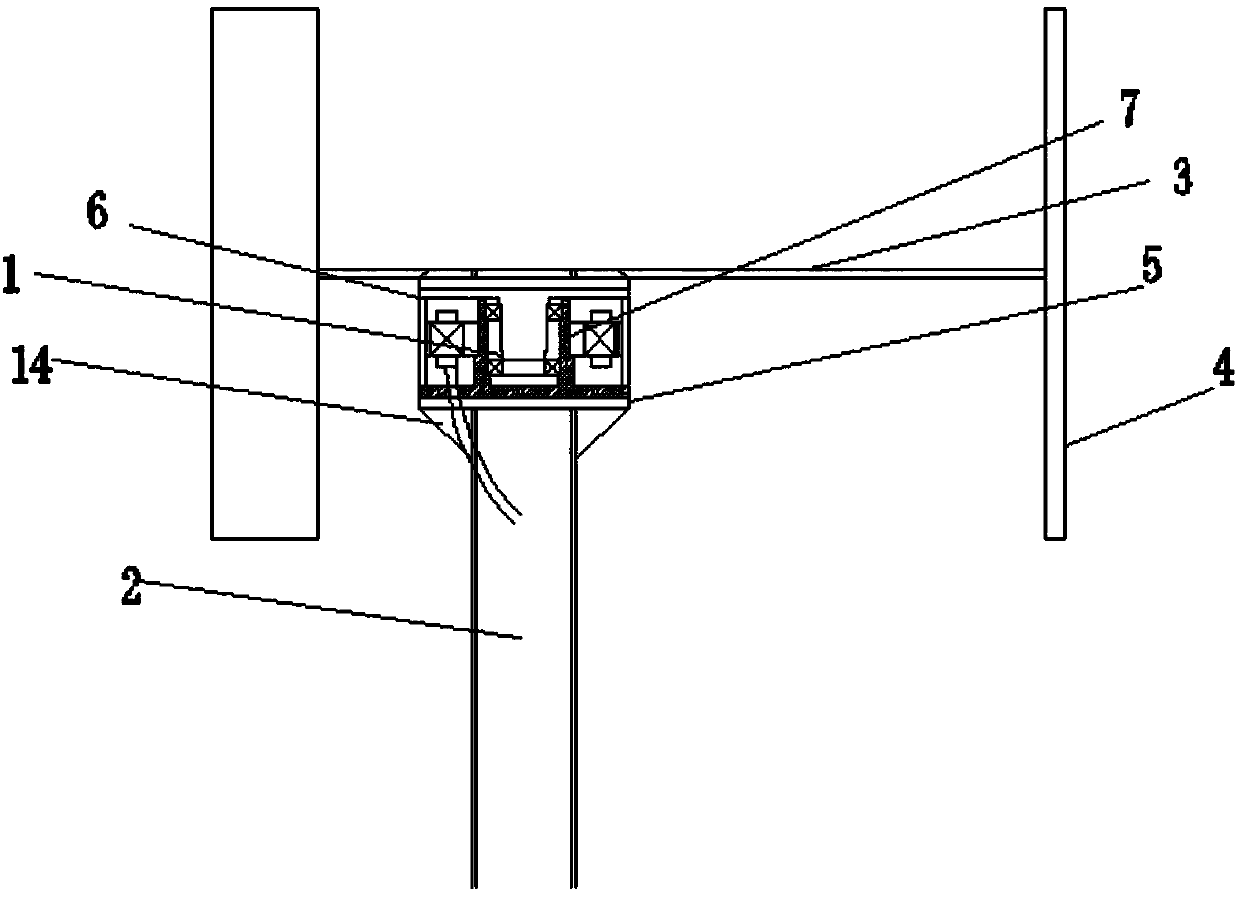
[0025] Such as figure 1 As shown, a wind power generation device provided by the present invention includes a generator 1, a vertical pole 2, a connecting rod 3 and blades 4, a mounting plate 5 is installed above the vertical pole 2, and a mounting plate 5 is installed above the mounting plate 5 Generator 1, a plurality of connecting rods 3 are installed on the top of the generator 1, blades 4 are installed on the ends of the connecting rods 3, and the mounting plate 5 can facilitate the integrated installation of the generator 1, and at the same time facilitate replacement and maintenance. Ribs 14 can be connected between the mounting plate 5 and the pole 2 to improve stability.
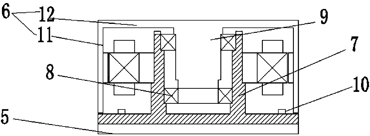
[0026] Among them, such as figure 2 As shown, the generator 1 includes a rotor 6, a stator 7, a bearing 8 and a rotating shaft 9, the stator 7 is fixed on the mounting plate 5 by a fastener 10, and the fastener 10 can be a fastening bolt or other fastening components, the middle part of the stato...
Embodiment 2
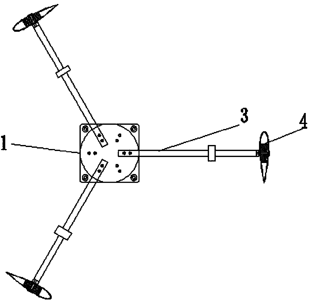
[0029] Such as image 3 As shown, the blade 4 is a hollow blade, and the outer surface of the blade 4 is arc-shaped, and a spacer 13 is arranged inside the blade 4, and the outer surface of the spacer 13 is arc-shaped, and the spacer 13 The upper and lower intervals are arranged, and the hollow blades are supported by pads 13 to ensure the stability of the hollow blades.
[0030] Wherein, the spacer 13 is provided with a bolt connection hole, and the spacer 13 is two pieces, arranged at intervals up and down, so as to ensure that the blade will not be twisted.
[0031] The shape of the blade in the invention adopts an aircraft airfoil with good aerodynamic performance, and the internal cavity of the blade adopts a box structure, which improves the strength and stability of the blade and can maximize the use of the lift characteristics of the airfoil.
Embodiment 3
[0033] Such as image 3 As shown, the connecting rod 3 can be an elastic telescopic rod. When it is first started, the speed is low, the centrifugal force is small, the telescopic rod is in a contracted state, the diameter of the blade track circle is small, and the solidity of the blade is large. The starting torque is larger at lower wind speeds, so that the fan can self-start at lower wind speeds; after starting, the centrifugal force increases, the telescopic rod extends, and the diameter of the blade track circle increases, thereby reducing the solidity of the blades, making the fan The tip speed ratio is increased, the aerodynamic efficiency of the fan is improved, and the blade diameter is increased to increase the windward area, increase the converted wind energy, and greatly increase the power generation; when encountering strong winds, due to the small blade solidity, the aerodynamic efficiency of the fan The stall performance is good. When the speed is controlled at...
PUM
 Abstract
Description
Claims
Application Information