Loading machine

A technology of loader and installation department, which is applied in the direction of lifting device, lifting frame, etc., which can solve the problems of installation and maintenance influence, the failure of lifting mechanism to lift, and the increase of the cost of the lift, so as to facilitate installation and maintenance, avoid safety hazards, and pass smoothly sexual effect

Inactive Publication Date: 2018-04-06
CHINA INTERNATIONAL MARINE CONTAINERS (GROUP) CO LTD +3
View PDF6 Cites 0 Cited by
  • Summary
  • Abstract
  • Description
  • Claims
  • Application Information

AI Technical Summary

Problems solved by technology

However, when the main platform is at a low position, the angle between the hydraulic oil cylinder of this lifting mechanism and the horizontal plane is too small, so that the lifting force in the vertical direction is too small, which easily causes the problem that the lifting mechanism cannot lift
If this kind of lifting mechanism is needed to realize the lifting of the main platform at a low position, it is necessary to increase the working pressure of the hydraulic system or increase the rod diameter of the oil cylinder to increase the lifting force of the oil cylinder, and increase the working pressure of the hydraulic system or enlarge the oil cylinder. The diameter of the rod will increase the pressure and displacement of the hydraulic main pump, and at the same time increase the power demand of the engine, so it is necessary to choose a hydraulic main pump with a larger displacement and pressure and a higher power engine, and at the same time, it is necessary to withstand pressure. Higher performance and larger diameter hydraulic lines, resulting in a significant increase in the cost of the lift
In addition, the increase of the rod diameter of the hydraulic cylinder and the increase of the overall specification of the hydraulic cylinder will lead to an increase in the installation space, and the installation and maintenance will also be affected.

Method used


Image

  • Loading machine
  • Loading machine
  • Loading machine

Examples


Embodiment approach 1

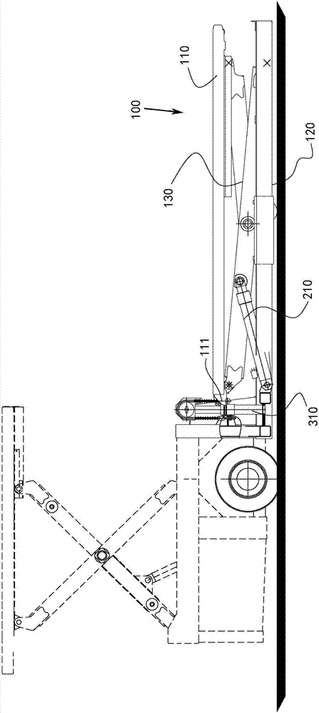
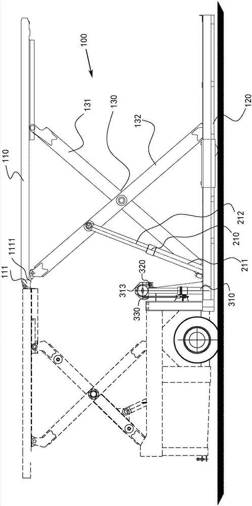
[0030] Refer to figure 1 , figure 1 Representatively shows a schematic structural diagram of a loader that can embody the principles of the present invention when it is in a working state, and specifically shows that the main platform 110 of the loader is in an unlifted working state. In this exemplary embodiment, the loader proposed in the present invention is an example of a cargo loader, and further, a cargo loader capable of transporting ultra-wide cargo is taken as an example for description. It is easy for those skilled in the art to understand that in order to apply the loader proposed by the present invention to other fields, various modifications, additions, substitutions, deletions or other changes are made to the following specific embodiments, and these changes are still It is within the scope of the principle of the loader proposed by the present invention.

[0031] Such as figure 1 As shown, in this embodiment, the loader proposed by the present invention mainly inc...

Embodiment approach 2

[0044] Refer to Figure 5 , Figure 5 Representatively shows another exemplary embodiment of a loader that can embody the principle of the present invention, and specifically represents that the main platform 110 of the loader is in an unlifted working state. In this exemplary embodiment, the main structures and control principles of the loader proposed by the present invention are substantially the same as those of the first embodiment. The differences between this embodiment and the first embodiment will be described in detail below in conjunction with the drawings.

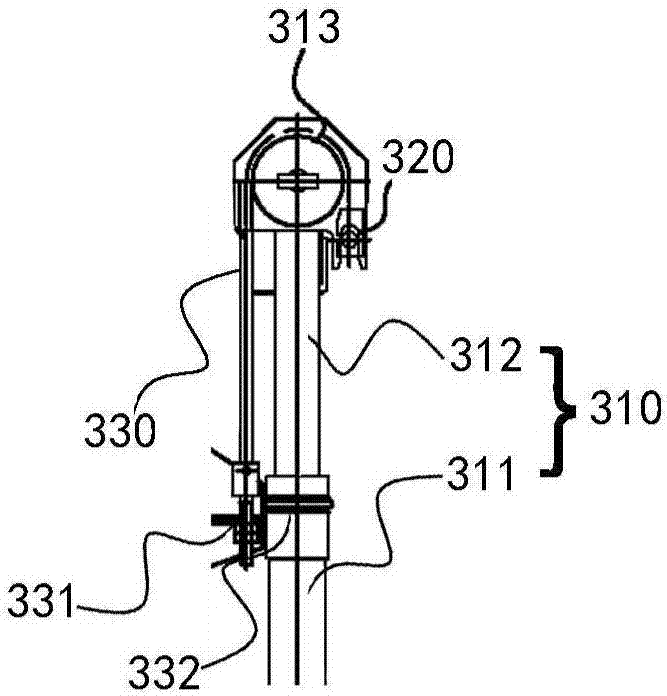
[0045] In this embodiment, the auxiliary lifting device is a third oil cylinder, and the mounting part and the lifting part of the auxiliary lifting device are the third cylinder 410 and the third telescopic rod of the third oil cylinder, respectively. The bottom of the third cylinder 410 is fixed to the base 120, and the third telescopic rod is telescopically arranged in the third cylinder 410 (and can be extende...


PUM


Abstract

The invention discloses a loading machine. The loading machine comprises a frame body, a main lifting device and an auxiliary lifting device. The frame body comprises a main platform, a pedestal and afork rack. The main platform is arranged on the pedestal through the fork rack in a liftable mode. The main lifting device is arranged between the pedestal and the main platform or the fork rack andhas a first lifting height. The auxiliary lifting device is arranged between the pedestal and the main platform or the fork rack and has a second lifting height, and the second lifting height is smaller than the first lifting height. The main lifting device is controlled by a control mechanism and used for driving the main platform to go up and down within the first lifting height, and the auxiliary lifting device is also controlled by the control mechanism and used for driving the main platform to go up and down within the second lifting height. According to the loading machine, the auxiliarylifting device matched with the main lifting device is arranged to provide sufficient lifting force for the main platform at the low position, there is no need to increase the working pressure of a hydraulic system or the rod diameter of an oil cylinder, the main platform can be lifted up and down stably, cost can be effectively reduced and meanwhile installation and maintenance are facilitated.

Description

Technical field [0001] The present invention relates to the technical field of loaders, and in particular to a loader with auxiliary lifting functions. Background technique [0002] The lifting mechanism of the existing cargo loader is mainly a mast cylinder chain type lifting mechanism or a lifting mechanism in which the lifting cylinder is located between the fork frame and the underframe. The lifting mechanism of the above-mentioned existing loaders has the following disadvantages. [0003] Gantry cylinder chain lifting mechanism. Because the hydraulic cylinders are arranged on the left and right sides of the main platform, the cylinder stroke is long, and the height of the cylinder and the lifting mechanism is higher than the table surface of the main platform, which easily blocks the transmission of ultra-wide cargo and allows the cargo of the main platform to pass Sex is affected. At the same time, when transporting ultra-wide cargo, the cargo is likely to collide with the ...

Claims


Application Information

Patent Timeline
Patent Type & Authority Applications(China)
IPC IPC(8): B66F9/22B66F9/12B66F7/08B66F9/065
CPCB66F7/08B66F9/065B66F9/127B66F9/22
Inventor 易文张晓东杨东升
Owner CHINA INTERNATIONAL MARINE CONTAINERS (GROUP) CO LTD
Why Eureka
Try Eureka