Semi-automatic stamp making machine

A kind of stamping machine and semi-automatic technology, applied in the field of stamping machines, can solve the problems of physical exhaustion and waste of time of printing users, and achieve the effect of saving printing time and reducing workload.

Inactive Publication Date: 2018-06-01
陈晓辉
View PDF6 Cites 2 Cited by
  • Summary
  • Abstract
  • Description
  • Claims
  • Application Information

AI Technical Summary

Problems solved by technology

This method does not have a significant difference in speed for a single or a small number of files, but for multiple files, not only will the user be physically tired, but also a waste of time

Method used


Image

  • Semi-automatic stamp making machine
  • Semi-automatic stamp making machine
  • Semi-automatic stamp making machine

Examples


specific Embodiment 1

[0073] This embodiment is a concrete embodiment of the semi-automatic stamp machine of the present invention.

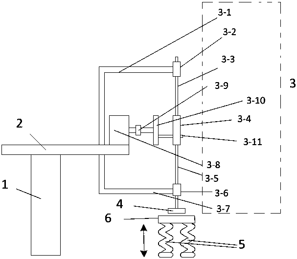
[0074] The semi-automatic stamp machine of the present embodiment, structural representation is as figure 1 As shown, it includes a bracket 1, a stage 2, a continuously controlled reciprocating intermittent motion platform 3, a stamp 4 and a two-dimensional paper clamping structure 6;

[0075] The support 1 is placed vertically, the top of the support 1 is equipped with a loading platform 2, and the front end of the loading platform 2 is equipped with a continuous control reciprocating intermittent motion platform 3;

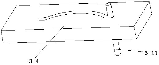
[0076] The continuous control reciprocating intermittent motion platform 3 includes an upper fixed bracket 3-1, an upper fixed end 3-2, an upper rod 3-3, a moving block 3-4, a lower rod 3-5, and a lower fixed end 3-6, Lower fixed support 3-7, motor 3-8, shaft coupling 3-9, T-type turntable 3-10 and limit projection 3-11; The position of described uppe...

specific Embodiment 2

[0083] This embodiment is a specific embodiment of the spring of the present invention.

[0084] In a semi-automatic stamp machine, the bottom of the two-dimensional paper clamping structure 6 is provided with a supporting spring 5, and when the supporting spring 5 is only compressed by the two-dimensional paper clamping structure 6, the upper surface of the two-dimensional paper clamping structure 6 is higher than that of the stamp 4 In the lowest moving position, when the support spring 5 is fully compressed, the upper surface of the two-dimensional paper clamping structure 6 is lower than the lowest moving position of the stamp 4 .

[0085] When the semi-automatic stamp machine is in motion, under the rotation of the motor 3-8, the moving block 3-4 realizes the reciprocating intermittent movement; The intermittent movement drives the stamp 4 to reciprocate intermittently; during the downward movement of the stamp 4, the two-dimensional paper clamping structure 6 is pressed,...

specific Embodiment 3

[0086] This embodiment is a specific embodiment determined by the continuous control of the reciprocating intermittent motion platform of the present invention.

[0087] The continuous control reciprocating intermittent motion platform of this embodiment, on the basis of specific embodiment one or specific embodiment two, such as Figure 4 The flow shown further defines the motion block 3-4 to determine the parameters by the following steps:

[0088] In the semi-automatic stamping machine, the movement block 3-4 determines parameters through the following steps:

[0089] Step a, according to the running time t of the motion block 3-4 1 and dead time t 2 ,Sure:

[0090] The running cycle is T=t 1 +t 2 , the operating angle is and the stagnation angle is

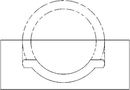
[0091] Step b, according to the running distance s of the moving block, determine the radius r of the inferior arc slot;

[0092] r=s / 2;

[0093] Step c, according to the radius r of the inferior arc through groove...


PUM


Abstract

The invention discloses a semi-automatic stamp making machine, and belongs to the technical field of stamp making machines. The semi-automatic stamp making machine comprises a support, a carrying table, a continuous control reciprocating intermittent movement platform, a stamp, springs and a two-dimensional paper clamping structure. The semi-automatic stamp making machine has the advantages that the stamp of the semi-automatic stamp making machine with the structure can be automatically lifted up and dropped down, accordingly, stamp affixing actions can be automated, workload on stamp users can be relieved, and the stamp use time can be saved; components can carry out reciprocating intermittent movement under the condition that a motor rotates at a constant speed, a movement state and a halt state can be seamlessly connected with each other, the motor does not need to be accurately controlled to be matched with movement parameters of the components, and the difficulty of high-precisioncontrol can be lowered; clamping structures and paper accommodating plates of the paper clamping structure can be adjusted when the semi-automatic stamp making machine works, accordingly, stamp papercan be relatively fixedly positioned, clear stamp making effects can be realized, and abrasion of the semi-automatic stamp making machine can be reduced to the greatest extent.

Description

technical field [0001] The semi-automatic stamp machine of the invention belongs to the technical field of stamp machines. Background technique [0002] In an office environment, we often need to stamp materials or documents. Traditional stamping is done manually. In this way, there is no obvious difference in speed for a single file or a small number of files, but for multiple files, not only will the user be physically tired, but also a waste of time. If a kind of semi-automatic or full-automatic stamping machine can be arranged, it will reduce the workload of stamping people and save printing time simultaneously. Contents of the invention [0003] In view of the above problems, the patent of the present invention discloses a semi-automatic stamping machine, the stamp can be lifted and lowered automatically, realizing the automation of stamping action, reducing the workload of the stamper and saving the time of stamping. [0004] The purpose of patent of the present i...

Claims


Application Information

Patent Timeline
Patent Type & Authority Applications(China)
IPC IPC(8): B41K3/04
CPCB41K3/04
Inventor 不公告发明人
Owner 陈晓辉
Why Eureka
Try Eureka