Wind wheel and air blower applying wind wheel

A wind wheel and joint technology, which is applied in the blower field, can solve the problems of weak welding between the wind blade and the bottom panel, easy occurrence of missing welding, and large jump of the wind wheel, so as to improve welding efficiency, reduce welding points, and reduce welding points Effect

Pending Publication Date: 2018-06-29
ZHONGSHAN BROAD OCEAN
View PDF0 Cites 5 Cited by
  • Summary
  • Abstract
  • Description
  • Claims
  • Application Information

AI Technical Summary

Problems solved by technology

[0003] The purpose of the present invention is to provide a wind wheel and a blower for its application, which solves the problem in the prior art that due to the plane welding between the wind blade and the bottom panel, there are many welding points, and the welding leakage is prone to occur during welding, which leads to the problem of the wind blade and the bottom panel. Welding between the panels is not firm, so that the wind wheel jumps greatly during operation and the balance is poor

Method used


Image

  • Wind wheel and air blower applying wind wheel
  • Wind wheel and air blower applying wind wheel
  • Wind wheel and air blower applying wind wheel

Examples


Embodiment 1

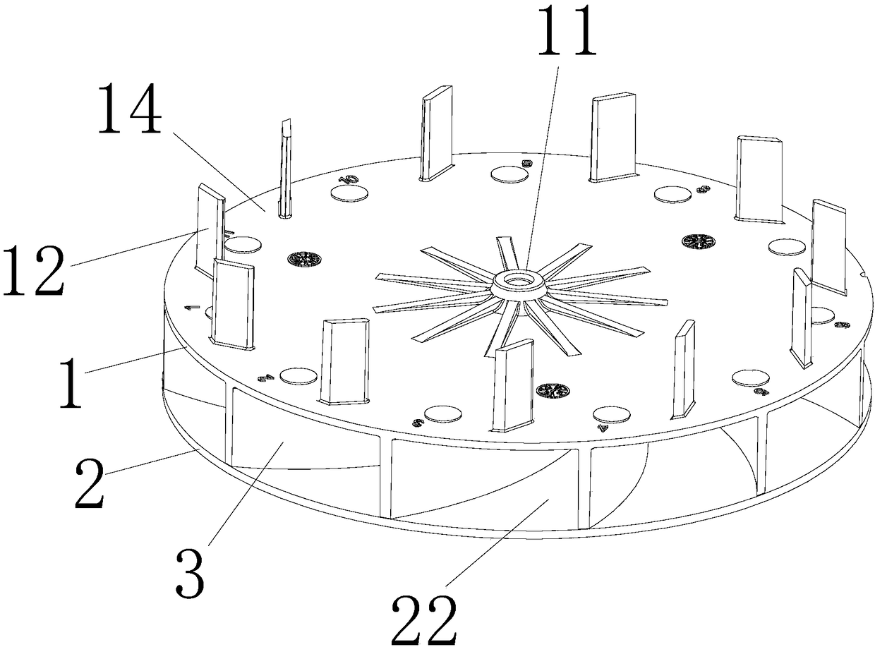
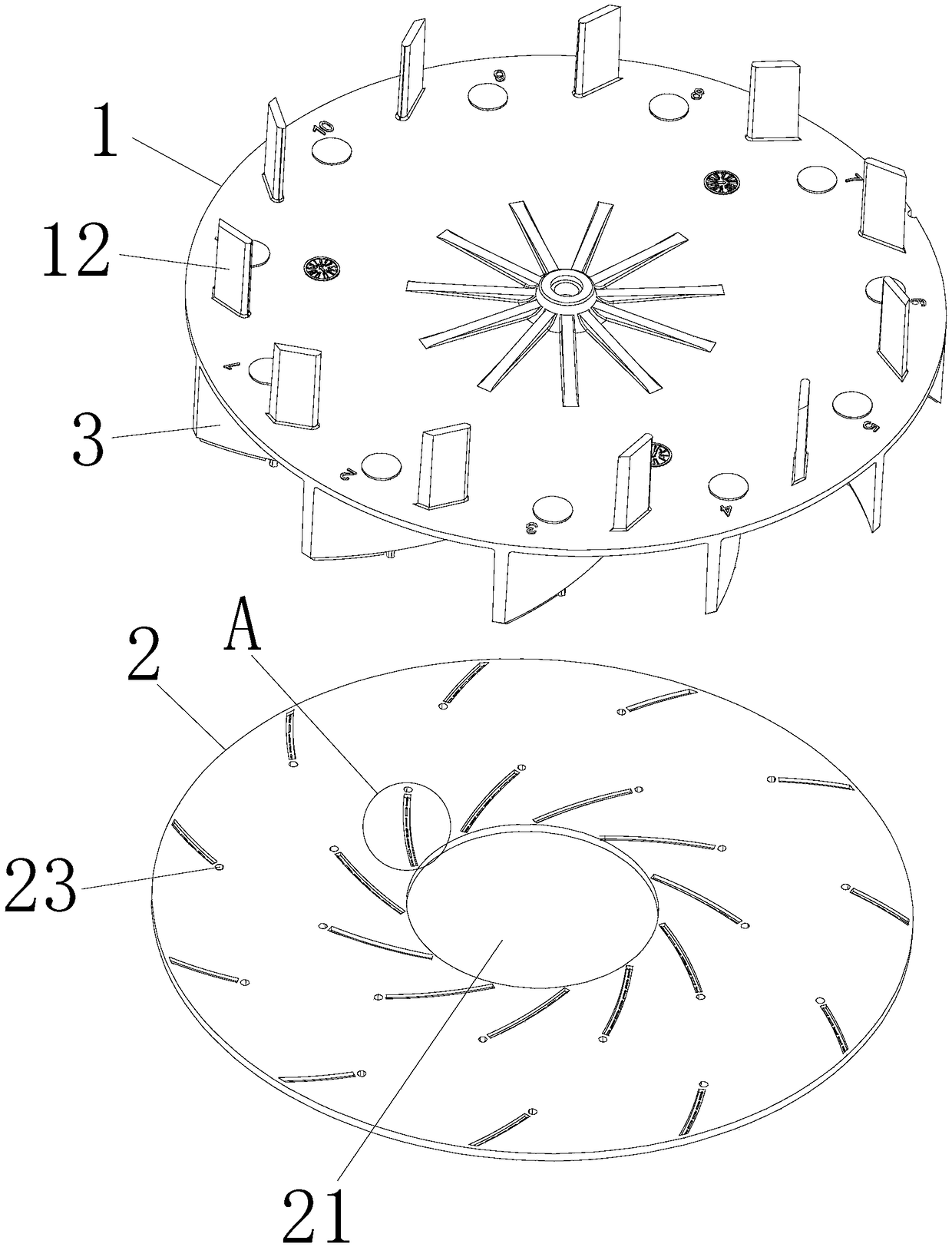
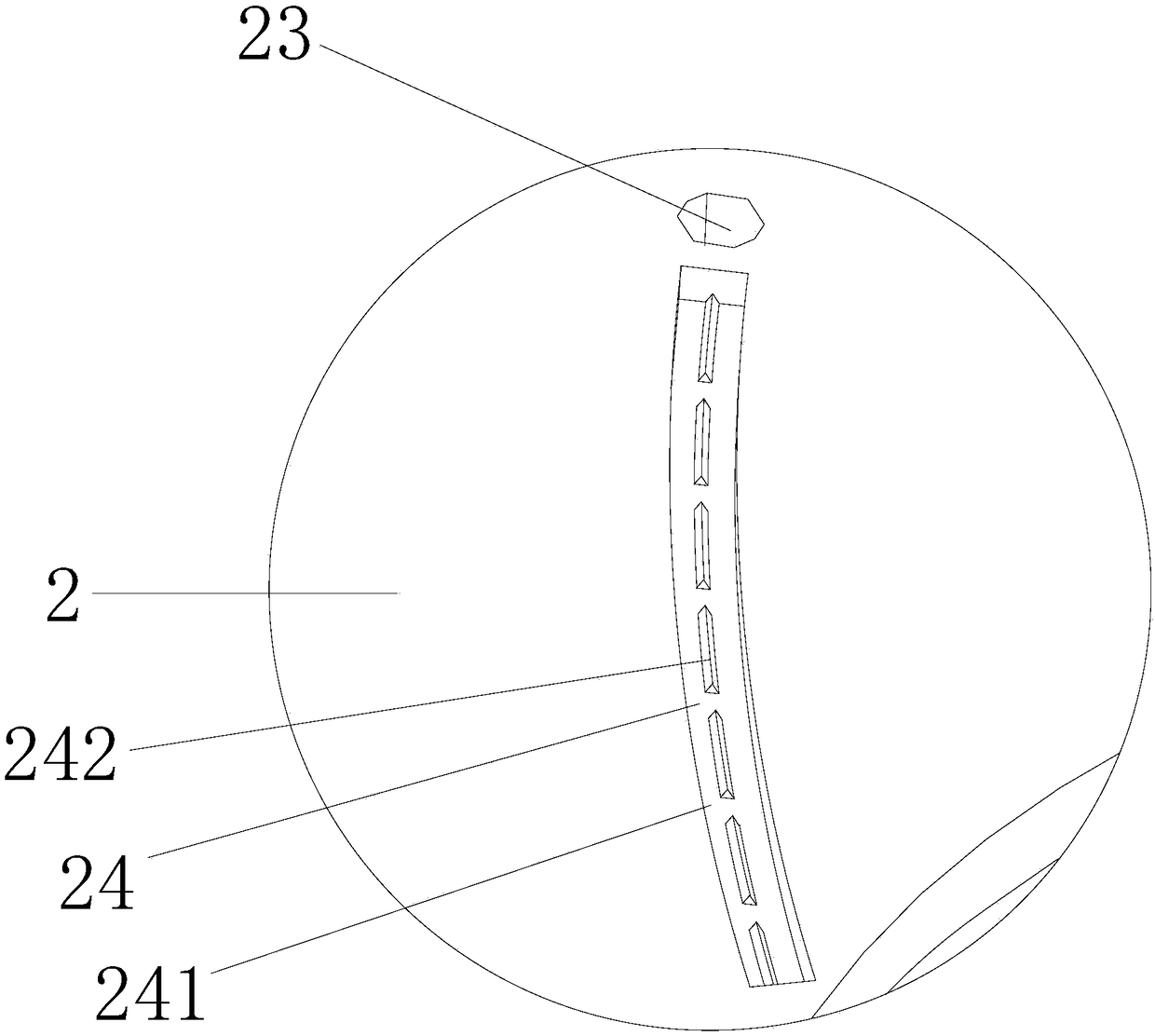
[0031] Such as Figure 1 to Figure 8 As shown, the present embodiment is a wind wheel, comprising a top panel 1 and a bottom panel 2 with several wind blades 3, several wind blades 3 protrude from the lower end surface 13 of the top panel 1, and several wind blades 3 are connected with The top panel 1 is integrally injection-molded, and several wind blades 3 are located between the top panel 1 and the bottom panel 2, and an air inlet 21 is arranged in the middle of the bottom panel 2, and an air duct 22 is formed between two adjacent wind blades 3, and the center of the top panel 1 A connection seat 11 connected to the motor shaft is provided, and several positioning columns 32 protrude from the end surface 31 connected to the bottom panel 2 of the wind blade 3, and the bottom panel 2 is provided with the positioning columns 32 passing through the mounting holes 23 and welded The wind blade 3 and the bottom panel 2 are fixed together, and the end surface 31 of the wind blade 3...

Embodiment 2

[0039] Such as Figure 9 and Figure 10 As shown, a blower includes a volute 4, a cover plate 5, a motor 6, a motor shaft 7 and a wind wheel 9, the volute 4 and the cover plate 5 are installed and connected together to form a cavity 8, and the wind wheel 9 is installed in the cavity 8 Inside, the volute 4 is provided with an air outlet 41, and the cover plate 5 is provided with an air inlet 51, and the feature is that the wind wheel 9 is any one of the wind wheels 9 described in the first embodiment.


PUM


Abstract

The invention discloses a wind wheel and an air blower applying the wind wheel. The wind wheel comprises a top panel provided with a plurality of wind blades and a bottom panel. The multiple wind blades protrude out of the lower end face of the top panel, and the multiple wind blades and the top panel are integrally formed through injection molding. The multiple wind blades are located between thetop panel and the bottom panel. An air inlet is formed in the middle of the bottom panel. An air flue is formed between every two adjacent wind blades. A connecting base connected with a motor shaftis arranged in the center of the top panel. A plurality of positioning columns protrude out of the end faces, connected with the bottom panel, of the wind blades. The bottom panel is provided with installing holes for the positioning columns to penetrate, and the wind blades and the bottom panel are fixed together through welding. The end faces of the wind blades are further provided with a plurality of first bosses. The bottom panel is provided with grooves matched with the first bosses. The first bosses are embedded in the grooves, the first bosses and the grooves are combined together through welding, welding points are reduced, and the problem about solder skips is reduced; and the welding precision is improved, welding is firm, and the problems that during wind wheel running, jumpingis great, and balance performance is poor are effectively solved.

Description

Technical field: [0001] The invention relates to a wind wheel and a blower for its application. Background technique: [0002] The existing wind wheel includes a top panel, a bottom panel, and several wind blades installed and connected between the top panel and the bottom panel. An air inlet is arranged in the middle of the bottom panel, and an air duct is formed between two adjacent wind blades. A cavity is formed on the inside of the top of the wind blade, and an air outlet is formed on the outside of the wind blade. A connecting seat connected to the motor shaft is arranged in the center of the top panel, and several auxiliary pieces uniformly distributed around the axial direction protrude from the edge of the top panel. Wind blades, auxiliary wind blades and several wind blades are distributed on both sides of the top panel, and one end surface of the wind blades is combined with the bottom panel by welding. Since the wind blades and the bottom panel are plane welded, ...

Claims


Application Information

Patent Timeline
Patent Type & Authority Applications(China)
IPC IPC(8): F04D29/28F04D29/30F04D29/62
CPCF04D29/281F04D29/30F04D29/624
Inventor 林炎虎雷威张淼
Owner ZHONGSHAN BROAD OCEAN
Why Eureka
Try Eureka