Sponge cutting device

A sponge cutting and cutting knife technology, which is applied in metal processing, dust removal, cleaning methods and utensils, etc., can solve the problem of uneven cutting surface of the sponge, achieve good cutting effect, improve the processing environment, and improve the cutting quality.

Active Publication Date: 2018-07-13
重庆致昌塑胶制品有限公司
View PDF5 Cites 6 Cited by
  • Summary
  • Abstract
  • Description
  • Claims
  • Application Information

AI Technical Summary

Problems solved by technology

[0004] The present invention intends to provide a sponge cutting device to solve the problem of uneven cutting surface of the sponge

Method used


Image

  • Sponge cutting device
  • Sponge cutting device

Examples


Embodiment Construction

[0023] The following is further described in detail through specific implementation methods:

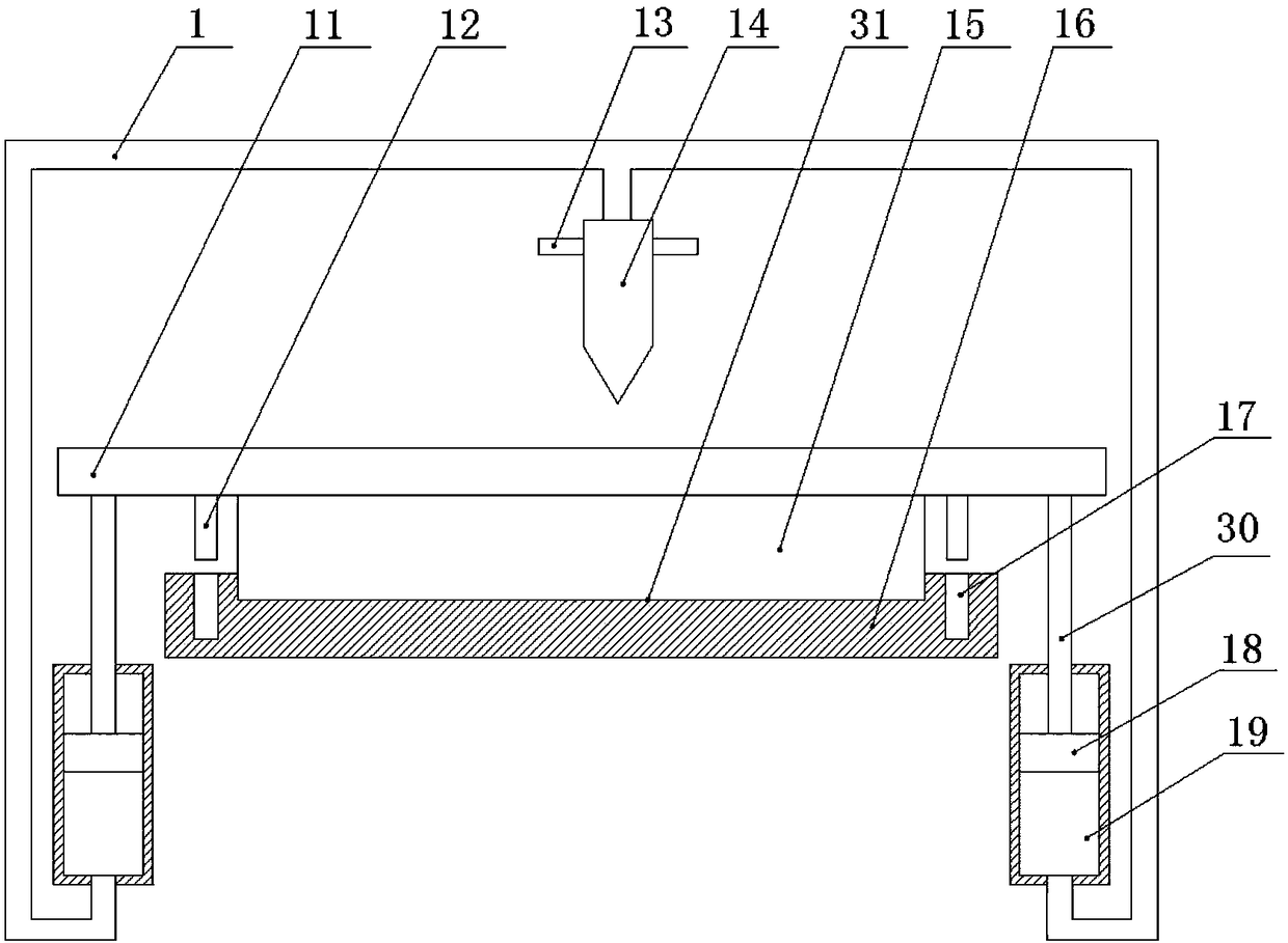
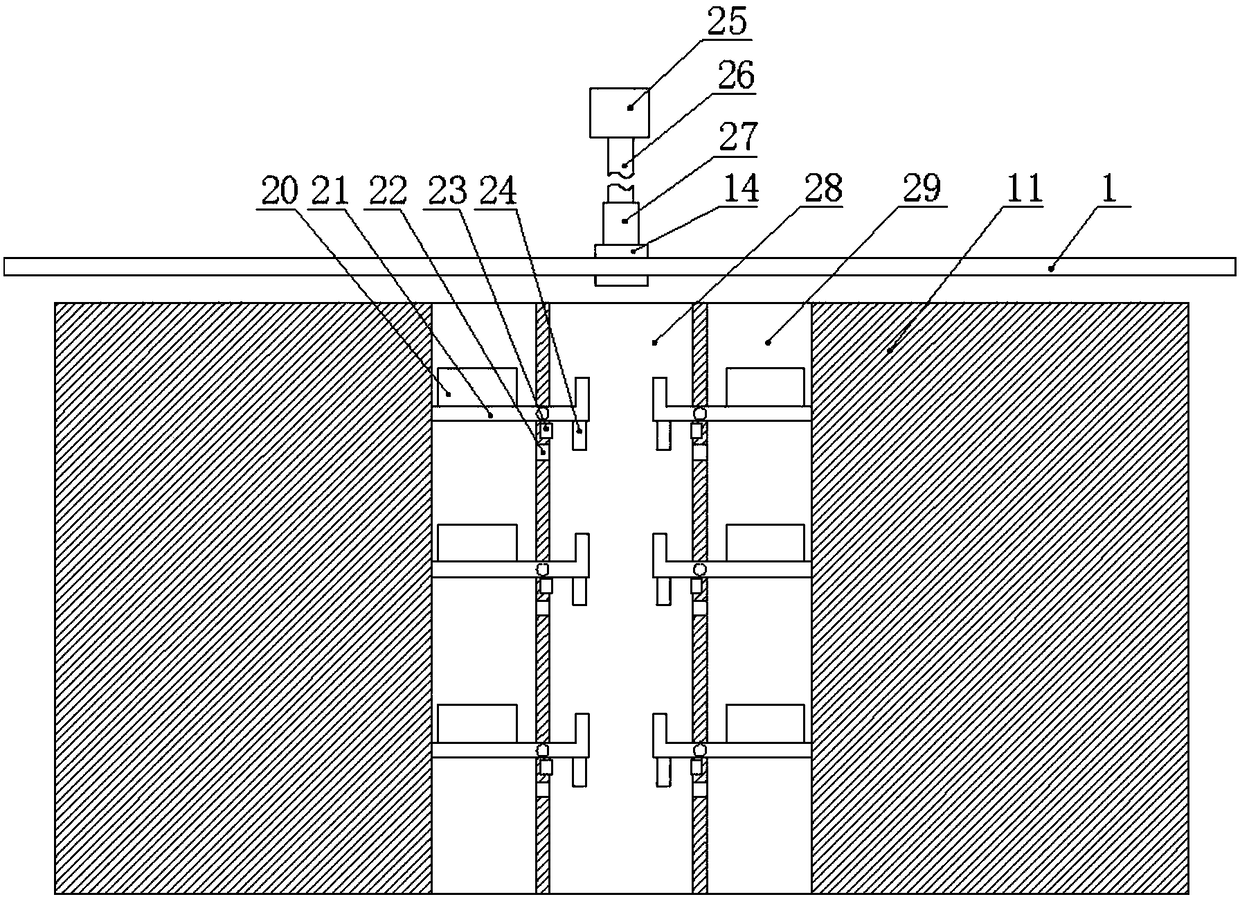
[0024] The reference signs in the drawings of the description include: straw 1, pressing plate 11, latch 12, pole 13, cutter 14, sponge 15, placing plate 16, jack 17, piston 18, water storage pipe 19, electrostatic plate 20, pendulum Rod 21, positioning hole 22, time delay switch 23, positioning rod 24, cylinder 25, piston rod 26, fixed sleeve 27, through hole 28, collecting tank 29, push rod 30, placement groove 31.

[0025] figure 2 In the middle, the top is the rear, and the bottom is the front.

[0026] Such as figure 1 As shown, a sponge cutting device of the present invention includes a placement plate 16 made of an electromagnet, the placement plate 16 is provided with a placement groove 31 for placing the sponge 15, and an iron pressing plate 11 is slidably installed above the placement plate 16, A fixing mechanism is installed between the pressing plate 11 and the placin...


PUM


Abstract

The invention relates to a cutting device, in particular to a sponge cutting device. The sponge cutting device comprises a storing plate made of an electromagnet. An iron press plate is slidably arranged above the storing plate. A fixing mechanism is arranged between the press plate and the storing plate. The two ends of the press plate are vertically provided with push rods. Water storage pipes are arranged below the push rods. The water storage pipes are internally and slidably provided with pistons. The pistons are connected with the push rods. A hollow cutting knife is slidably arranged above the press plate. A suction pipe is arranged between the cutting knife and the water storage pipes in a communicating mode. The cutting knife is provided with a fixed sleeve. One side of the pressplate is provided with an air cylinder. The air cylinder can be connected with the fixed sleeve. The press plate is provided with a through hole for allowing the cutting knife to penetrate through. The through hole is provided with a dedusting mechanism. The sponge cutting device can solve the problem that the cutting surface of sponge is uneven.

Description

technical field [0001] The invention relates to a cutting device, in particular to a sponge cutting device. Background technique [0002] Sponge is a porous material with good water absorption and can be used to clean items. Commonly used sponges are made from wood cellulose fibers or expanded plastic polymers. The application of sponge involves various industries, including automobile industry, battery industry, cosmetics industry, bust underwear manufacturing industry and high-end furniture manufacturing industry. [0003] In order to adapt to the application of different occasions, the sponge usually needs to be cut. Existing sponge cutting mostly uses a motor to directly drive a cutter to cut the sponge. This cutting method has the following defects: 1. Because the sponge has a certain elasticity, the cutter is not easily stressed during the cutting process, which may easily cause the sponge to be cut. The phenomenon of uneven surface requires secondary cutting, which...

Claims


Application Information

Patent Timeline
Patent Type & Authority Applications(China)
IPC IPC(8): B26D1/08B26D7/02B26D7/00B08B15/04
CPCB08B15/04B26D1/08B26D7/00B26D7/025
Inventor 彭军
Owner 重庆致昌塑胶制品有限公司
Why Eureka
Try Eureka