a squeeze pump

A technology of squeezing pumps and pump bodies, which is applied in the direction of lubricating pumps, mechanical equipment, engine components, etc., which can solve the problems of easily damaged pistons, and achieve the effects of reducing vibration, changing flow velocity, and good elasticity

Active Publication Date: 2019-11-05
NORTH CHINA UNIV OF WATER RESOURCES & ELECTRIC POWER
View PDF5 Cites 0 Cited by
  • Summary
  • Abstract
  • Description
  • Claims
  • Application Information

AI Technical Summary

Problems solved by technology

[0003] The technical problem to be solved by the present invention is: to overcome the technical problem that the piston of the piston squeeze pump in the prior art is easily damaged, and to provide a piston-free squeeze pump

Method used


Image

  • a squeeze pump

Examples


Embodiment Construction

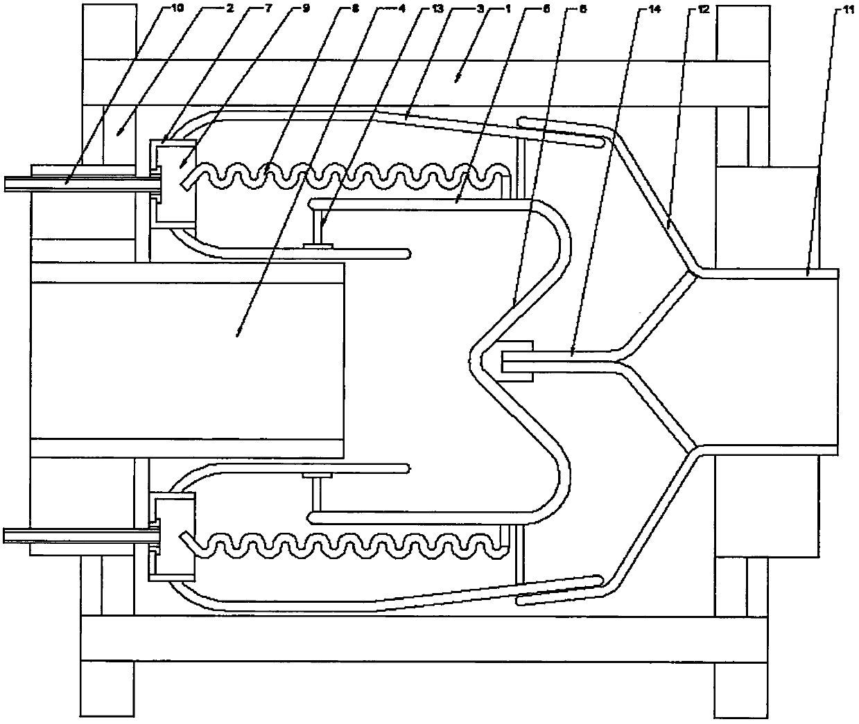
[0017] The present invention is described in further detail now in conjunction with accompanying drawing. These drawings are all simplified schematic diagrams, which only illustrate the basic structure of the present invention in a schematic manner, so they only show the configurations related to the present invention.

[0018] like figure 1 As shown, the present invention is a squeeze pump, which includes a pump casing, and a support cover is provided on both lateral sides of the pump casing, wherein a liquid inlet pipe is arranged on the left support cover, and the inlet The liquid pipe extends into the pump body shell, and an annular return cavity is arranged outside the liquid inlet pipe, and the axial end of the return flow chamber opens toward the left side of the pump body shell; the axial end of the liquid inlet pipe The part is also provided with a return cover; the inner wall of the return cover is sleeved on the inner wall of the return cavity, and an annular retur...


PUM


Abstract

The invention relates to an extrusion pump which comprises a pump shell. A liquid inlet pipeline is arranged on the left side of the pump shell; an annular reflow cavity is arranged on the outer partof the liquid inlet pipeline; a reflow housing is further arranged at the axial end part of the liquid inlet pipeline; an annular reflow clearance is arranged between an inner wall of the reflow housing and an inner side wall of the reflow cavity; the reflow housing is connected onto the liquid inlet pipeline through a support ring; a conical flow guiding part is arranged at the end part of the reflow housing; a water draining clearance is arranged on the outer side wall surface of the reflow cavity; a pressurizing cavity is arranged at the axial end part of the reflow cavity; an annular pressure discharging cavity is arranged in the pressurizing cavity; an annular shaking pipe is arranged in the pressure discharging cavity; a cross section of the shaking pipe is in a wave shape; an air inlet pipe is arranged at a sealed end of the pressure discharging cavity in an annular array way; a water draining pipeline is arranged on a support cover on the right side; a water draining cover witha tapered structure is arranged on the water draining pipeline; a necking end of the water draining cover is connected onto the water draining pipeline; a flaring end of the water draining cover is slidably connected with the outer side wall surface of the reflow cavity; and an elastic connecting structure is arranged on the back part of a sealed end of the reflow housing.

Description

technical field [0001] The invention relates to a squeeze pump, which belongs to the field of hydraulic pump equipment. Background technique [0002] Squeeze pump, as a small flow pump, is often used to transport lubricating fluid on many machine tools and other equipment. Traditional squeeze pumps use piston reciprocating peristalsis to deliver lubricating fluid, but in many cases, lubricating fluid is generally It is recycled, so it is easy to mix metal impurities in the lubricating fluid, which can easily cause scratches on the piston and damage the water pump. Contents of the invention [0003] The technical problem to be solved by the present invention is: to overcome the technical problem that the piston of the piston squeeze pump in the prior art is easily damaged, and to provide a piston-free squeeze pump. [0004] The technical solution adopted by the present invention to solve its technical problems is: [0005] A squeeze pump, comprising a pump body casing, a ...

Claims


Application Information

Patent Timeline
Patent Type & Authority Patents(China)
IPC IPC(8): F16N13/00
CPCF16N13/00
Inventor 王文吴林峰唐明奇
Owner NORTH CHINA UNIV OF WATER RESOURCES & ELECTRIC POWER
Why Eureka
Try Eureka