Air supply assembly, and indoor unit with same, for cabinet air conditioner

A component and fan technology, which is applied in the field of cabinet-type air conditioner indoor units, can solve the problems of large temperature difference between the center and the edge of the airflow, low flow velocity at the edge, and high flow velocity in the middle, so as to improve user experience, smooth flow, and good user experience. Effect

Active Publication Date: 2018-09-14
QINGDAO HAIER AIR CONDITIONER GENERAL CORP LTD +1
View PDF13 Cites 20 Cited by
  • Summary
  • Abstract
  • Description
  • Claims
  • Application Information

AI Technical Summary

Problems solved by technology

[0002] In the prior art, the air guide duct connected with the volute air duct of the centrifugal fan either extends in a straight line or gradually expands relative to the outer contour of the impeller, and the airflow blown out is an annular airflow with a high velocity in the middle and a low velocity at the edges. Especially when this kind of centrifugal fan and air guide duct are applied to the indoor unit of the air conditioner, the user will feel a large temperature difference between the center and the edge of the airflow

Method used


Image

  • Air supply assembly, and indoor unit with same, for cabinet air conditioner
  • Air supply assembly, and indoor unit with same, for cabinet air conditioner
  • Air supply assembly, and indoor unit with same, for cabinet air conditioner

Examples


Embodiment 1

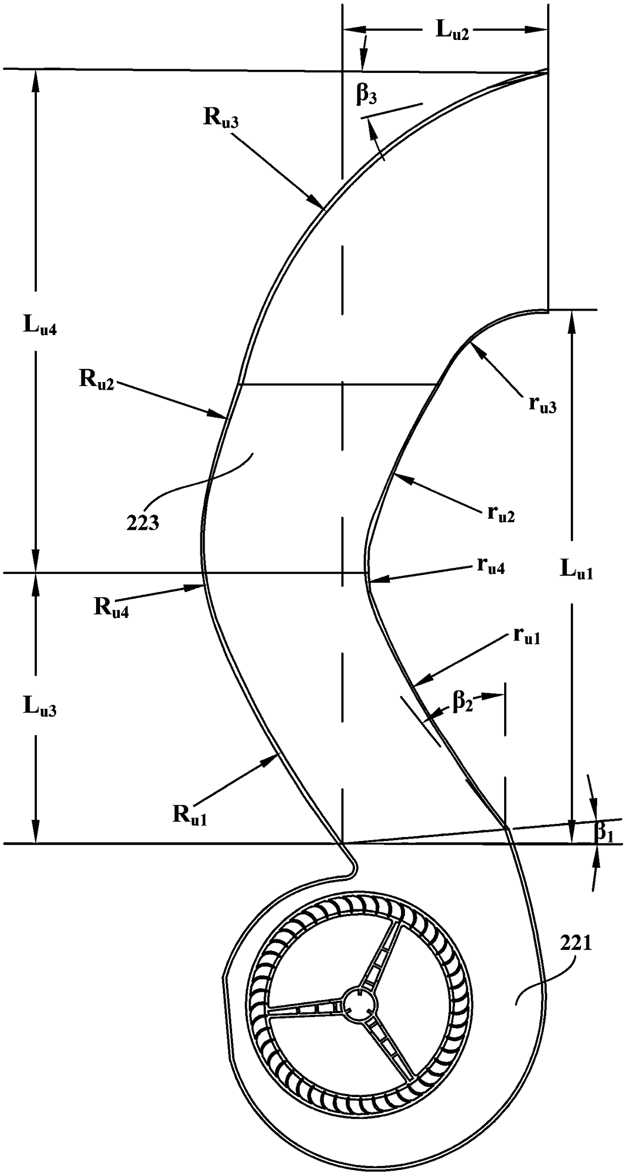
[0080] The fan air outlet of the centrifugal fan of the first air supply assembly 220 extends from front to back toward the direction close to the impeller 2211, and the angle β between it and the horizontal plane 1 is 5°. Angle β between the tangent line of the front edge of the first front arc passing through the fan outlet and the vertical direction 2 is 38°. Radius r of the first front arc u1 is 800mm. Radius r of the second front arc u2 It is 775mm. The angle of the third front arc is 57°. Radius r of the third front arc u3 is 75mm. The distance L between the end of the third front arc and the rear edge of the fan outlet in the front-to-back direction u2 110mm, the distance L from the rearward edge of the fan outlet in the vertical direction u1 is 500mm. Radius R of the first rear arc u1 It is 1100mm. Radius R of the second rear arc u2 It is 410mm. The distance from the center of the second rear arc to the end of the third rear arc in the front-rear directio...


PUM


Abstract

The invention provides an air supply assembly. The air supply assembly comprises a centrifugal fan and an air guide member used for guiding and conveying the airflow blown out from the centrifugal fanto an indoor environment. The outlet section of the centrifugal fan is located at the front side of the volute tongue section of the centrifugal fan. The air guide member defines a flow guide air channel extending in a direction departing from an impeller of the centrifugal fan from an air outlet port of the fan, and the forward sidewall and the backward sidewall of the flow guide air channel areconfigured to extend along a front convex curve and a rear convex curve separately; the two transversal sidewalls of the flow guide air channel are configured to extend in the vertical direction; andeach of the front convex curve and the rear convex curve is a curve bulged backwards. The flow guide air channel comprises a diffusion section extending in a manner of gradually expanding from each axial edge of the air outlet port of the fan, and a flow stabilization section extending in a manner of gradually shrinking from the extending end of each diffusion section, and lower noise is achieved, and the flow speed difference value of the airflow blown out from the centre and the edge of an air outlet port of the flow guide air channel is low, so that good user experience is achieved.

Description

technical field [0001] The invention relates to the field of air treatment, in particular to an air supply assembly and a cabinet-type air conditioner indoor unit with the air supply assembly. Background technique [0002] In the prior art, the air guide duct connected with the volute air duct of the centrifugal fan either extends in a straight line or gradually expands relative to the outer contour of the impeller, and the airflow blown out is an annular airflow with a high velocity in the middle and a low velocity at the edges. Especially when the centrifugal fan and the air guide duct are applied to the indoor unit of the air conditioner, the user will feel a large temperature difference between the center and the edge of the airflow. Contents of the invention [0003] It is an object of the first aspect of the present invention to provide a blower assembly with uniform wind speed. [0004] A further object of the first aspect of the present invention is to increase th...

Claims


Application Information

Patent Timeline
Patent Type & Authority Applications(China)
IPC IPC(8): F24F1/00F24F13/08F24F13/20F24F13/24F24F13/30
CPCF24F1/0022F24F13/081F24F13/20F24F13/24F24F13/30F24F2013/247Y02B30/70
Inventor 单翠云王永涛王晓刚李英舒尹晓英
Owner QINGDAO HAIER AIR CONDITIONER GENERAL CORP LTD
Why Eureka
Try Eureka