Exhaust fan

An exhaust fan and casing technology, which is applied to mechanical equipment, machines/engines, liquid fuel engines, etc., can solve the problems of the dead angle of the air inlet grille, the high installation of the exhaust fan, and difficulty in cleaning, so as to prevent secondary pollution and save money. The effect of cleaning time and improving cleaning efficiency

Inactive Publication Date: 2018-09-28
佛山市土禾设备实业有限公司
View PDF6 Cites 14 Cited by
  • Summary
  • Abstract
  • Description
  • Claims
  • Application Information

AI Technical Summary

Problems solved by technology

[0006] The clutch device includes a pressing block and a No. 1 spring; a mounting hole is arranged at one end of the rotating shaft of the motor; the pressing block is slidably installed in the mounting hole through the No. 1 spring; the cross section of the pressing block is arch-shaped, and the pressing block The arch-shaped cross section is parallel to the axis of the motor shaft; the connecting shaft is provided with an insertion hole near the end of the clutch device; the inner wall of the insertion hole is provided with a connection groove matched with the pressing block; the rotation shaft of the motor can be inserted into the insertion hole The pressing block is used to connect the motor shaft and the connecting shaft; the cross section of the pressing block is arch-shaped to ensure that the rotating shaft of the motor can be easily inserted into the socket hole, and because the two sides of the pressing block are planes, the connection with the socket hole The side of the groove can be fitted to transmit torque; when the motor shaft is inserted into the socket hole, the pressing block is compressed in the mounting hole, and the extension length of the electric cylinder can be adjusted to ensure the axial direction of the motor shaft inserted into the socket hole. The position is accurate. Driven by the rotation of the motor shaft, the pressing block rotates to the position corresponding to the connecting groove. Under the action of the No. 1 spring force in the installation hole, the pressing block pops out just to match the connecting groove to realize the transmission of torque; the clutch device It realizes that the dust removal device can be automatically connected and disconnected when the motor is running, and completes the work of automatically cleaning the exhaust fan, which solves the problems of too high installation of the exhaust fan, troublesome disassembly, and difficult cleaning of the dead angle of the air inlet grille, and saves at the same time Labor cleaning costs and cleaning time

Method used


Image

  • Exhaust fan
  • Exhaust fan
  • Exhaust fan

Examples


Embodiment approach

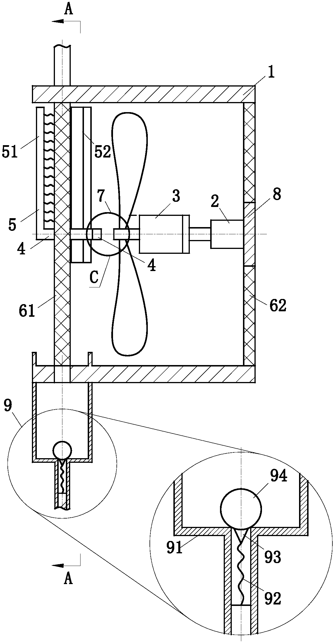
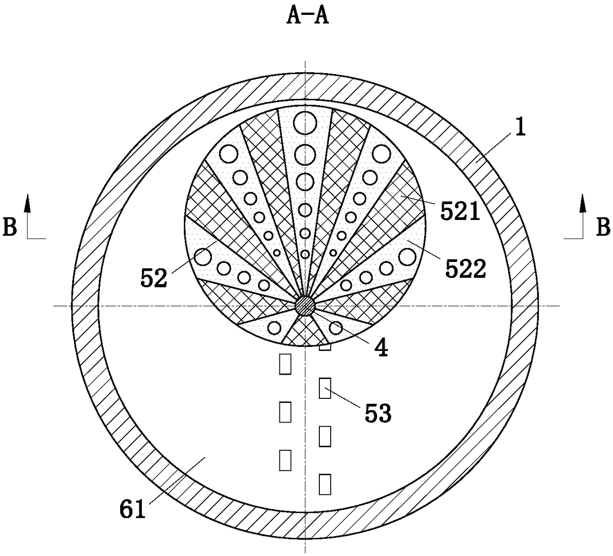
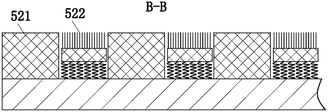
[0028] As an embodiment of the present invention, the dust removal device 5 includes a brush board 51, a wiper board 52, and a water squeeze block 53. The outside of the wind screen cover 61; the wiper 52 is arranged on the inside of the air intake screen 61, and the wiper 52 is used to clean the inside of the air intake screen 61; the water squeezing block 53 is arranged on the inside of the air intake screen 61 , the water squeeze block 53 is used to cooperate with the sponge block 521 on the wiper blade 52 to realize the removal of sewage on the sponge block 521; the brush plate 51 is fixedly connected with the wiper blade 52 through the connecting shaft 4; the wiper blade The plate 52 is disc-shaped, and the wiper blade 52 is mounted eccentrically on the connecting shaft 4; the surface of the wiper blade 52 near the side of the air intake net cover 61 is fixedly mounted with interval radial sponge blocks 521, adjacent to each other. There are brush plates 522 between the s...


PUM


Abstract

The invention belongs to the technical field of exhaust fans, and particularly relates to an exhaust fan. The exhaust fan comprises a machine shell, an electric cylinder, a motor, a fan blade, a connecting shaft, a dust removal device, an air inlet mesh cover, an air outlet mesh cover, a clutch device, a mounting plate and a drainage device; the air inlet mesh cover is fixedly connected to the inner wall of the left end of the machine shell, and the air outlet mesh cover is fixedly connected to the inner wall of the right end of the machine shell; a first opening is formed in the center of theair outlet mesh cover, and the electric cylinder is fixedly installed in the first opening through the mounting plate; and the non-output end of the motor is fixedly connected to the end part of thecylinder rod of the electric cylinder; the clutch device matched with the dust removal device is arranged at the end of the rotating shaft of the motor; the dust removal device is rotationally arranged at the center of the air inlet mesh cover through a connecting shaft; and a spraying pipe is arranged above the air inlet mesh cover, and the drainage device is arranged below the air inlet mesh cover. The exhaust fan is mainly used for cleaning the mesh cover of the exhaust fan, the mesh cover can be automatically cleaned, and the cleaning efficiency is improved.

Description

technical field [0001] The invention belongs to the technical field of exhaust fans, in particular to an exhaust fan. Background technique [0002] The exhaust fan is a type of air-conditioning appliance that is driven by a motor to rotate the blades to drive the airflow to exchange indoor and outdoor air. Also known as ventilator. The purpose of exhaust is to remove indoor dirty air, adjust temperature, humidity and sensory effects. Since the exhaust fan is generally fixedly installed on the top of the room, a lot of dust will accumulate on the exhaust fan after long-term use, which is inconvenient to clean, and the dust will affect the working efficiency of the exhaust fan. [0003] There are also some technical solutions for exhaust fans in the prior art. For example, a Chinese patent with application number 201610465854.6 discloses an exhaust fan with an automatic cleaning device, including a casing, and a water tank is arranged on the top of the casing. A controller ...

Claims


Application Information

Patent Timeline
Patent Type & Authority Applications(China)
IPC IPC(8): F04D25/08F04D29/70F04D29/00
CPCF04D25/08F04D29/002F04D29/703
Inventor 邵瑞张家俊杨柳
Owner 佛山市土禾设备实业有限公司
Why Eureka
Try Eureka