Device for precisely adjusting steel supporting pre-exerted axial force of foundation pit and loading method thereof

A steel support and foundation pit technology, which is applied in excavation, infrastructure engineering, construction, etc., can solve problems such as effective stability, low construction efficiency of adjustment devices, and inability to pre-add axial force for precise adjustment, so as to avoid failure and improve construction efficiency. , the effect of simple operation

Active Publication Date: 2018-11-16
YUNNAN JIANTOU FOUND ENG CO LTD
View PDF4 Cites 8 Cited by
  • Summary
  • Abstract
  • Description
  • Claims
  • Application Information

AI Technical Summary

Problems solved by technology

[0005] The purpose of the present invention is to provide a device for accurately adjusting the pre-applied axial force of foundation pit steel supports and its loading method, so as to solve the problems of low construction efficiency of the existing adjustment device and the inability to accurately adjust and effectively stabilize the pre-applied axial force

Method used


Image

  • Device for precisely adjusting steel supporting pre-exerted axial force of foundation pit and loading method thereof
  • Device for precisely adjusting steel supporting pre-exerted axial force of foundation pit and loading method thereof

Examples


Embodiment 1

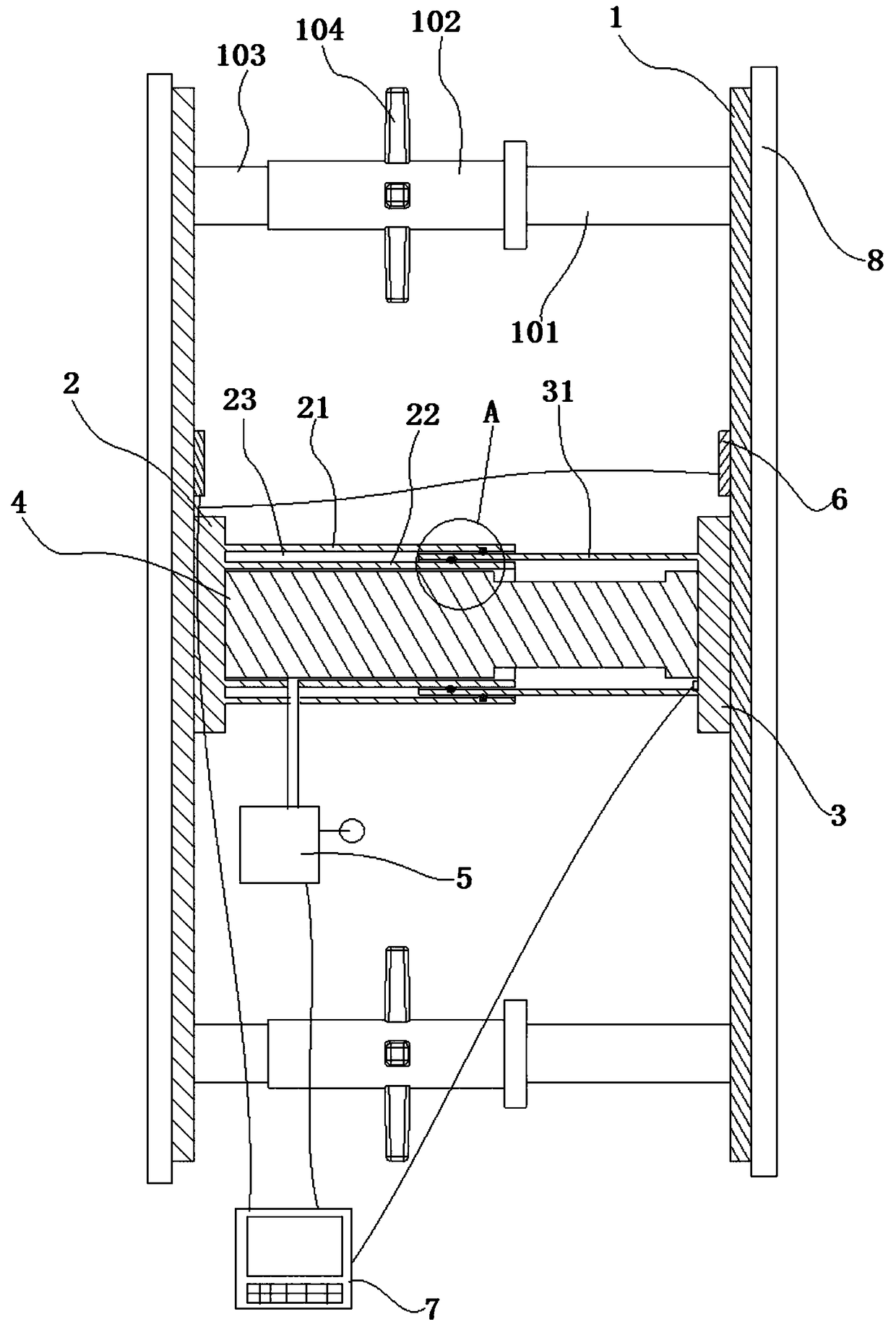
[0022] figure 1 It shows: a device for accurately adjusting the pre-loaded axial force of the foundation pit steel support, which is characterized in that it includes a fixed steel plate 1, a left loading slot 2, a right loading slot 3, a hydraulic jack 4, a hydraulic pump 5, a force sensor 6, a displacement Sensor, control panel 7 and auxiliary positioning device; the fixed steel plate 1 is provided with two pieces and is respectively fixed on the connecting beam 8 on both sides by bolts, and the fixed steel plate 1 is provided with a load cell 6; the left loading groove 2 One end is fixed on the fixed steel plate 1 on one side, the other end is composed of an outer cylinder 21 and an inner cylinder 22, the hydraulic jack 4 is fixed inside the inner cylinder 22, and an accommodation chamber 23 is formed between the inner wall of the outer cylinder 21 and the outer wall of the inner cylinder 22; One end of the right loading tank 3 is fixed on the fixed steel plate 1 on the oth...

Embodiment 2

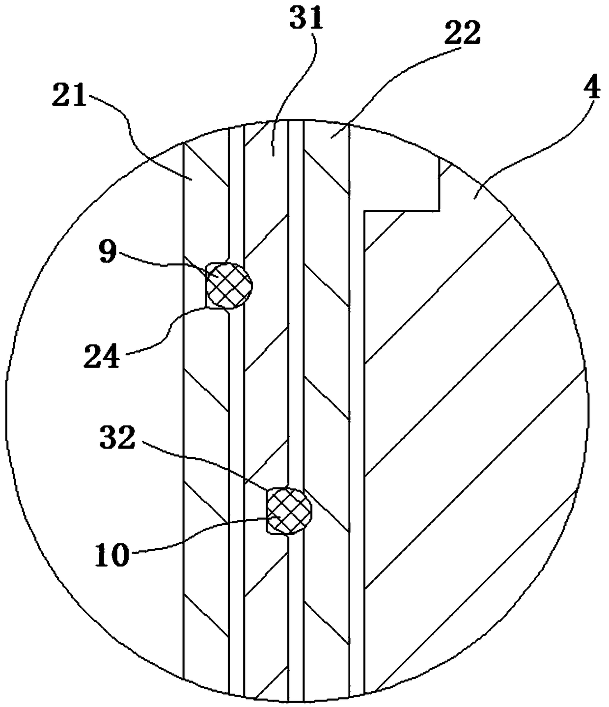
[0026] In order to further optimize the technical solution in Example 1, the inner wall of the cylinder 31 described in this example is concaved inward to form a first groove 32, and the first rubber ring 10 is clamped in the first groove 32, The inner diameter of the first rubber ring 10 is adapted to the outer diameter of the inner cylinder 22; the inner wall of the outer cylinder 21 is concaved to form a second groove 24, and the second rubber ring 9 is clamped in the second groove 24. The inner diameter of the rubber ring 9 is compatible with the outer diameter of the cylinder body 31 . Such as figure 2 As shown, the first rubber ring 10 is clamped between the cylinder body 31 and the inner cylinder 22, and the second rubber ring 9 is clamped between the cylinder body 31 and the outer cylinder 21 to limit the movement track of the cylinder body 31 and avoid the occurrence of diameters. direction displacement, while avoiding the direct contact between the cylinder body 31 a...

Embodiment 3

[0028] In order to further optimize the technical solution in Embodiment 1 or 2, the number of auxiliary positioning devices in this embodiment is 4 sets, which are respectively located on the four corners of the fixed steel plate 1 . The applied axial pressure is stabilized by 4 auxiliary positioning devices, making the support more stable and reliable.


PUM


Abstract

The invention discloses a device for precisely adjusting a steel supporting pre-exerted axial force of a foundation pit and a loading method thereof and relates to the technical field of building foundation pit bracing. The assembled device is fixed between two connecting tie beams, an axial force value needing to be exerted is set through a control panel, the adjusting device is started, a hydraulic jack ejects and compresses fixing steel plates with the value 18%-22% of the pre-exerted axial force value under the effect of a hydraulic pump, and the fixing steel plates produce relative displacement. When a force measuring sensor feeds back that the axial force exerted to the fixing steel plate reaches a set value 18%-22% of the pre-exerted axial force value, the hydraulic pump stops actions, the hydraulic jack increases 8%-12% of pre-exerted axial force value based on an original pressure value to exert pressure on the fixing steel plates after the pressure is stabilized for 5-10 minutes, the fixing steel plates are stabilized for 5-10 minutes after the fixing steel plates do not move, and the operation is repeated in this way. Finally, the axial pressure value between the two fixing steel plates reaches 60%-70% of the pre-exerted axial force value through one-time loading, connecting sleeves are adjusted after stabilization for 0.5-1 hour are ejected and compressed on the endfaces of fixing columns, and thus the loading process is completed.

Description

technical field [0001] The invention relates to the technical field of building foundation pit support, in particular to a device for accurately adjusting the pre-loaded axial force of foundation pit steel supports and a loading method thereof. Background technique [0002] During the excavation of the foundation pit, the support structure in the foundation pit plays an important role in maintaining the stability of the foundation pit. The traditional foundation pit support structure adopts a reinforced concrete structure, which has the disadvantages of slow construction speed, long maintenance time, and the need to dismantle it later, which is not conducive to energy conservation and environmental protection. In contrast, the steel support structures that have emerged in recent years generally have the advantages of convenient construction, fast speed, prestressing, and reusability, which are in line with the national development concept of energy conservation and environme...

Claims


Application Information

Patent Timeline
Patent Type & Authority Applications(China)
IPC IPC(8): E02D17/04
CPCE02D17/04
Inventor 张延杰许利东李振雄张骏潘延连王晓曙涂伟曹慧吴俊鹏朱贝贝苏元
Owner YUNNAN JIANTOU FOUND ENG CO LTD
Why Eureka
Try Eureka