Feeding device and method for cattle farms

A technology for farms and troughs, applied in the field of animal husbandry, can solve the problems of cattle malnutrition and feed waste, achieve the effects of saving feed, reducing labor intensity, and ensuring feed safety

Inactive Publication Date: 2019-01-11
李莉 +2
View PDF5 Cites 0 Cited by
  • Summary
  • Abstract
  • Description
  • Claims
  • Application Information

AI Technical Summary

Problems solved by technology

[0003] The purpose of the present invention is to provide a feeding device and method for cattle farms that save feed and ensure that cattle take in reasonable nutrition in order to overcome the problem that the cattle troughs in the prior art are likely to cause feed waste and cause malnutrition in cattle

Method used


Image

  • Feeding device and method for cattle farms
  • Feeding device and method for cattle farms
  • Feeding device and method for cattle farms

Examples


Embodiment 1

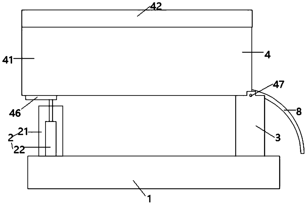
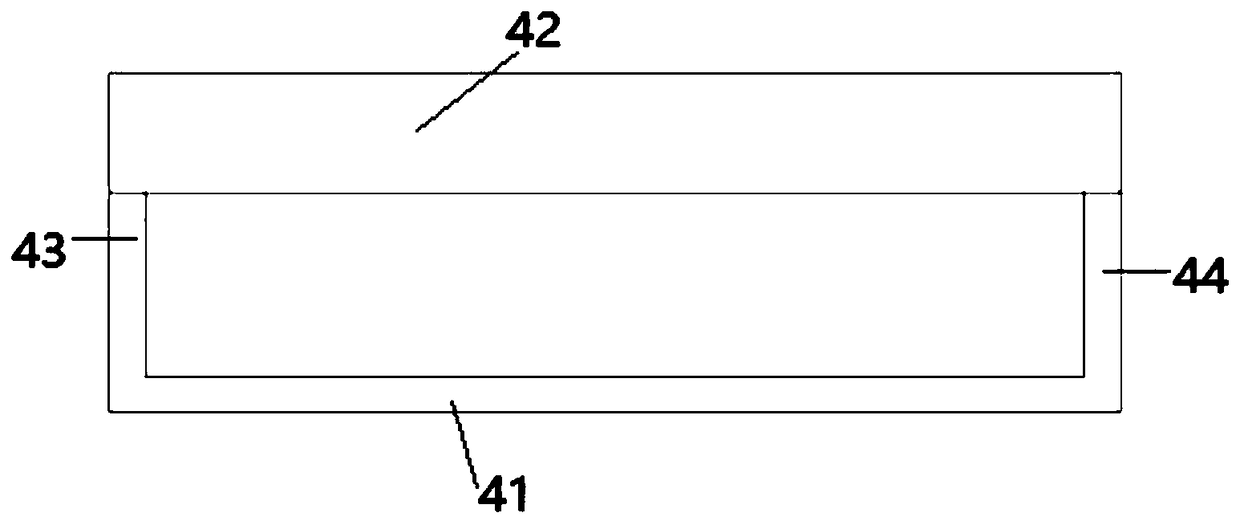
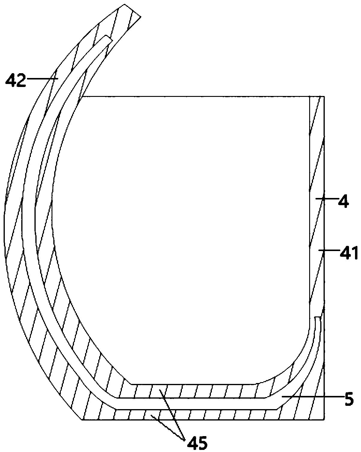
[0040] Such as figure 1 The illustrated embodiment is a feeding device for a cattle farm, comprising a base 1, a left support frame 2 and a right support frame 3 arranged on the base, and the horizontal sections arranged on the left support frame and the right support frame are rectangular trough 4; as figure 2 , image 3 As shown, the trough includes a front side wall 41, a rear side wall 42, a left side wall 43, a rear side wall 44 and a U-shaped bottom plate 45. The height of the position is higher than the height of the position of the upper end of the other side walls; the rear side wall and the U-shaped bottom plate are provided with a cavity 5, and the rear side wall and the inner surface of the U-shaped bottom plate are provided with a plurality of passages communicating with the cavity. Each through hole is provided with a one-way valve that can spray air from the cavity, and the cavity is connected with the air pump 6 through a pipeline, such as Figure 4 As show...

Embodiment 2

[0048] Embodiment 2 includes all structure and method parts of embodiment 1, such as figure 1 Shown, embodiment 2 also comprises the guide pipe 8 that is located on the food trough, is located at the hanging bracket above the food trough, as Figure 5 Shown, be located at the water outlet pipe and agitator 9 that can spray water downwards on the hanging bracket; figure 1 As shown, the left support frame includes a vertical tube 21 and a cylinder 22 located in the vertical tube, the telescopic rod end of the cylinder stretches into a horizontal chute 46 located on the left side of the lower surface of the food trough, and the right support frame is connected to the food tank by a rotating shaft 47. The lower right part of the groove is connected by rotation; the suspension bracket is connected with the fixing part through the lifting device, and the fixing part is respectively connected with the water outlet pipe and the agitator, and the first electromagnetic valve 10 is arran...

Embodiment 3

[0055] Embodiment 3 includes all structure and method parts of embodiment 1, as Figure 6 As shown, embodiment 3 also includes a plurality of suction pipes 302 connected to the lower part of the outer cylinder, each suction pipe is connected with the suction pump 303, each suction pipe is connected with the fly box 304, and in the fly box Water and heating wire 305 are provided, and the fly box is connected with the sewer through a pipeline, and the pipeline is provided with a second electromagnetic valve 306, such as Figure 4 As shown, both the suction pump and the second solenoid valve are electrically connected to the controller.

[0056] Also include the following steps:

[0057] (7-1) Every other day, the controller controls the suction pump to work for 10 seconds to suck the flies in the outer cylinder into the fly collection box. After the controller controls the heating wire to heat for 2 minutes, it controls the second electromagnetic valve to open, and the After w...


PUM


Abstract

The invention discloses a feeding device and method for cattle farms. The feeding device includes a base, a left support frame and a right support frame arranged on the base, and a trough arranged onthe left support frame and the right support frame and having a rectangular horizontal section. The trough includes a front side wall, a back side wall, a left side wall, a right side wall and a U-shaped bottom plate, wherein the back side wall is an arc arched backward, and the upper end of the back side wall is located higher than the upper ends of the other side walls. The feeding device further includes a fly trapping structure which consists of a trumpet-shaped inner cylinder with a downward opening and an outer cylinder arranged outside the inner cylinder. A feeding attraction tray is arranged at the bottom of the inner cylinder. The feeding device and the feeding method have the characteristics as follows: feed can be saved; the nutrition intake of cattle is reasonable; and healthygrowth of cattle is ensured.

Description

technical field [0001] The invention relates to the technical field of animal husbandry, in particular to a feeding device and a method for a cattle farm that saves feed and ensures reasonable nutrition for cattle. Background technique [0002] Cattle especially like fresh feed. The cattle will eat the feed that has just been put into the trough. After some feed is left, the cattle will start to pick and choose. Check the concentrate to eat; arching and arching, the feed is easy to be arched out, resulting in a waste of feed, and eating too much concentrate can easily cause diarrhea and poor nutritional intake. Contents of the invention [0003] The purpose of the present invention is to provide a feeding device and method for cattle farms that save feed and ensure that cattle take in reasonable nutrition in order to overcome the problem that the cattle troughs in the prior art are likely to cause feed waste and cause malnutrition. . [0004] In order to achieve the abov...

Claims


Application Information

Patent Timeline
Patent Type & Authority Applications(China)
IPC IPC(8): A01K5/00A01K5/01
CPCA01K5/001A01K5/01
Inventor 不公告发明人
Owner 李莉
Why Eureka
Try Eureka