A multifunctional grinding device

A multi-functional, grinding machine technology, applied in grinding machines, grinding slides, grinding racks, etc., to achieve the effect of simple structure, improved flexibility and strong practicability

Active Publication Date: 2020-06-19
济南鑫金龙机械有限公司
View PDF9 Cites 0 Cited by
  • Summary
  • Abstract
  • Description
  • Claims
  • Application Information

AI Technical Summary

Problems solved by technology

But this kind of grinding device can only be used for grinding on the horizontal surface, and the use surface needs to be further strengthened

Method used


Image

  • A multifunctional grinding device
  • A multifunctional grinding device
  • A multifunctional grinding device

Examples


Embodiment 1

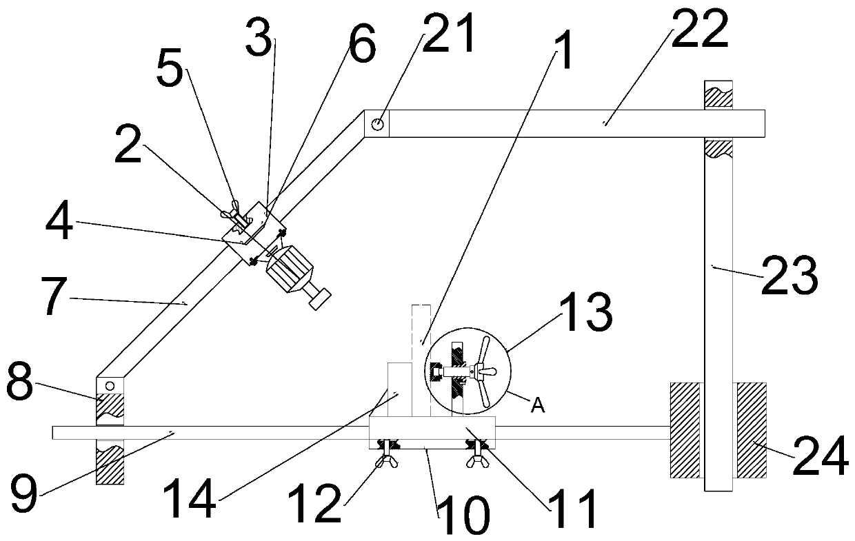
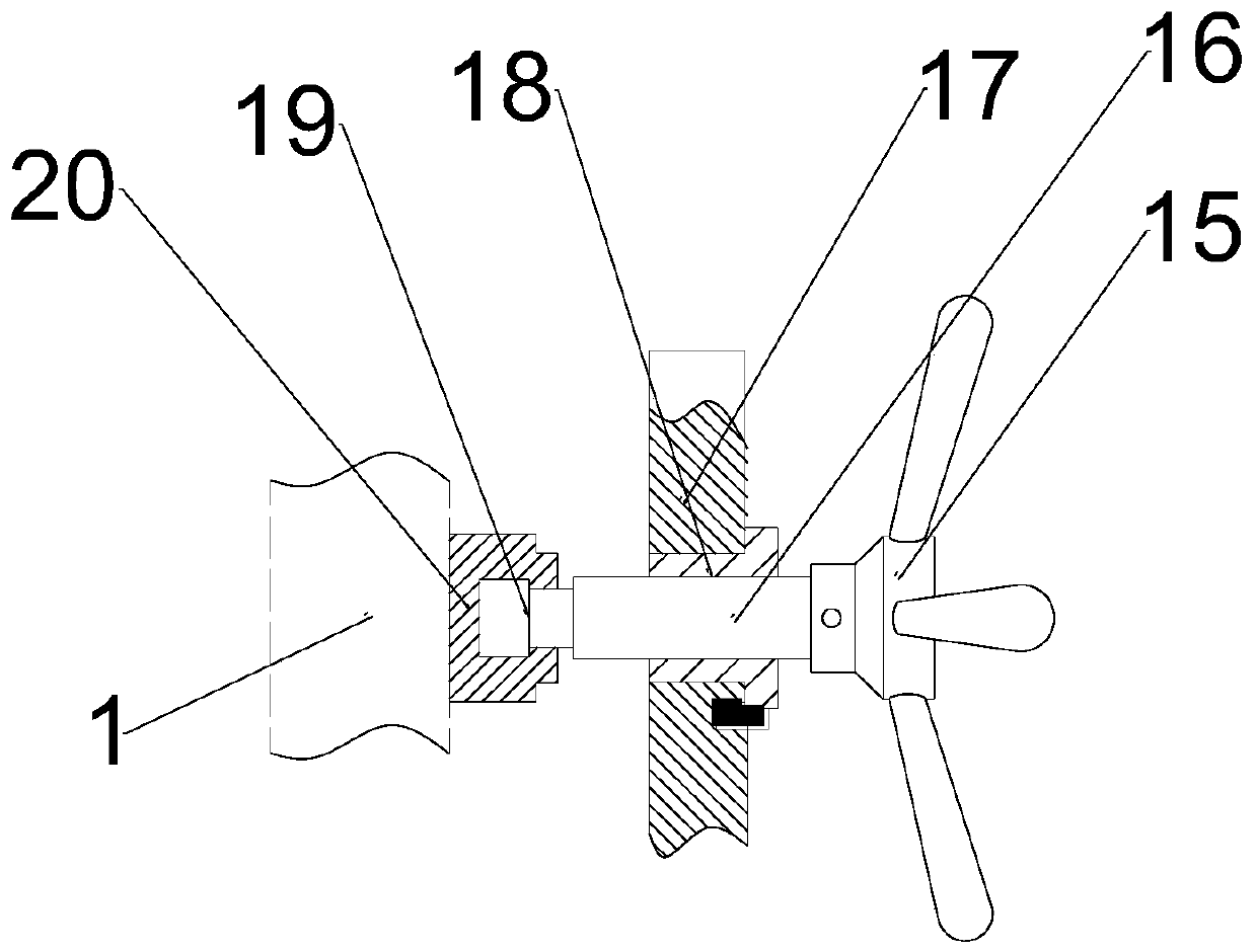
[0016] see figure 1 and figure 2 , a precise slotting device for mechanical parts, comprising a workpiece 1, a grinder 2 and a workpiece fastening mechanism 13, the grinder 2 is arranged above the workpiece 1, and the workpiece fastening mechanism 13 fastens the workpiece 1 Solid; the grinder 2 bolts are fixed on the grinder sliding mechanism 3, and the grinder slide mechanism 3 is slidably installed on the grinder slide rail 7, which can keep the grinder 2 at a certain inclination angle for grinding, and can perform chamfering Grinding operation, high grinding precision; the grinding machine sliding mechanism 3 includes a grinding machine mounting block 4, a grinding machine mounting block fastening bolt 5 and a handle 6, and the grinding machine 2 bolts are fixed on the grinding machine mounting block 4, The handle 6 is welded and fixed on the grinding machine mounting block 4, and the grinding machine mounting block fastening bolt 5 is also arranged on the grinding machin...

Embodiment 2

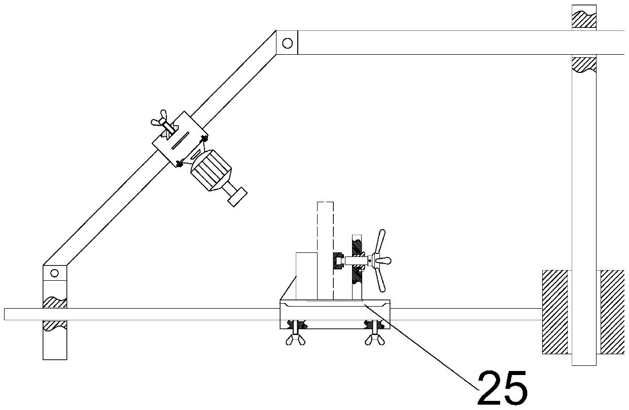
[0018] see image 3 Compared with Embodiment 1, the present embodiment 2 is only different in that the workpiece slider 11 includes the front and rear sliders 25, and the front and rear sliders 25 can make the workpiece fastening mechanism 13 slide back and forth, further improving the The flexibility of the grinding position of the grinding machine 2.

[0019] The working principle of the present invention is: adjust the grinding machine slide rail 7 to be fixed at any acute angle with the ground, then slide the grinding machine 2 on the grinding machine slide rail 7 to facilitate grinding at any angle, and simultaneously After the angle of the slide rail 7 of the grinding machine is fixed, the left and right positions of the grinding machine 2 can still be adjusted, which greatly improves the flexibility of the grinding position of the grinding machine 2; The fixed mechanism 13 can adjust the left and right positions of the workpiece 1, and further improve the flexibility o...


PUM


Abstract

The invention relates to the technical field of machining, in particular to a mechanical part accurate slotting device. The mechanical part accurate slotting device comprises a workpiece, a grinding machine and a workpiece fastening mechanism. The grinding machine is fixed to a grinding machine sliding mechanism through bolts. The grinding machine sliding mechanism is slidingly arranged on a grinding machine sliding rail. The upper end of the grinding machine sliding rail is rotationally arranged at the left end of an upper sliding rod of the grinding machine. The right end of the upper sliding rod is arranged at the upper end of a right support plate in a left-right sliding manner. The lower end of the right support plate is arranged on a lower right support plate in an up-down sliding manner. The left end of the lower right support plate is welded and fixed to the right end of a workpiece sliding rail. The left end of the workpiece sliding rail is arranged on a left lower support plate in a left-right sliding manner. A workpiece sliding mechanism is arranged on the workpiece sliding rail in a left-right sliding manner. The mechanical part accurate slotting device is extremely simple in structure and extremely low in manufacturing cost, the moving track of the grinding machine can be effectively controlled, rubdown, chamfering and other various grinding requirements are met, meanwhile, the mechanical part accurate slotting device can be applicable to components in various shapes, and practicability is extremely high.

Description

technical field [0001] The invention relates to the technical field of machining, in particular to a multifunctional grinding device. Background technique [0002] During the grinding process of parts, it is necessary to manually place the parts on the grinding device, and then move the parts back and forth, or manually use a grinder to grind the parts on the surface after fixing the parts, so the grinding accuracy is very low, and the grinding plane cannot be controlled Spend. [0003] Chinese patent (notification number: CN205497217U, announcement date: 2016.08.24) discloses a grinding device for processing hardware parts, including a base, and the two sides of the top of the base are respectively fixed with a lifting column and a grinding table, and the lifting column The top of one side is connected with one end of the fixed cross bar, and the bottom of the other end of the fixed cross bar is connected with a grinding device through the motor fixing frame. The grinding ...

Claims


Application Information

Patent Timeline
Patent Type & Authority Patents(China)
IPC IPC(8): B24B27/00B24B41/02B24B41/06
CPCB24B27/0084B24B41/02B24B41/06
Inventor 王飞
Owner 济南鑫金龙机械有限公司
Why Eureka
Try Eureka