

A fluid driving device and a urine drainage structure used for the same
A fluid-driven, fluid-based technology, applied in suction devices, hypodermic injection devices, pumping and pumping systems, etc., can solve the problems of large volume, adverse effects of liquid pipelines, and complex structure of liquid pumps, and achieve easy flow control and smooth urination , The effect of simple structure design
- Summary
- Abstract
- Description
- Claims
- Application Information
AI Technical Summary
Problems solved by technology
Method used
Image

Examples
Embodiment 1
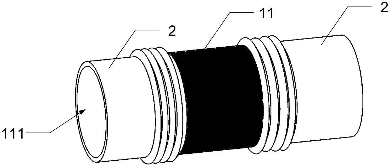
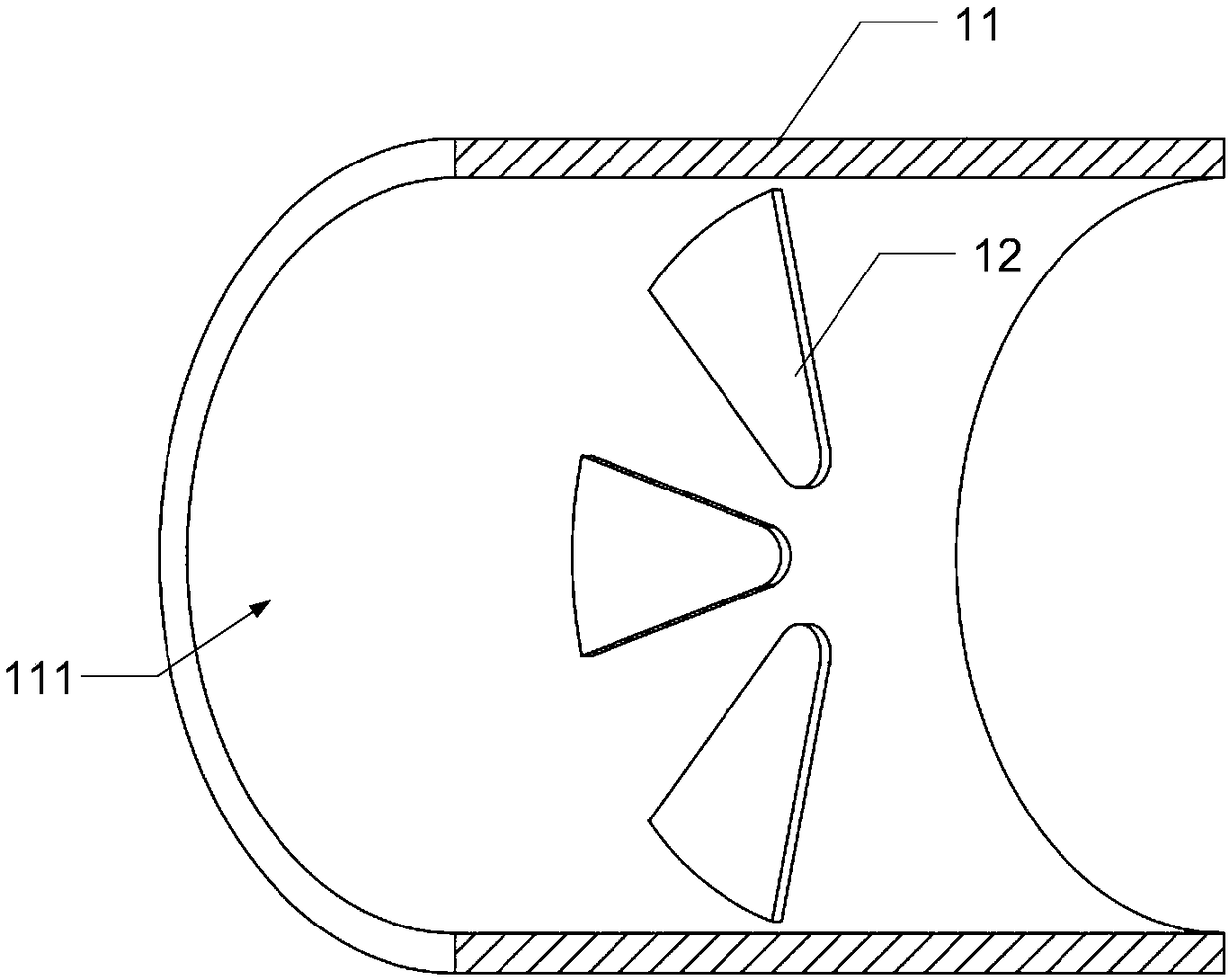
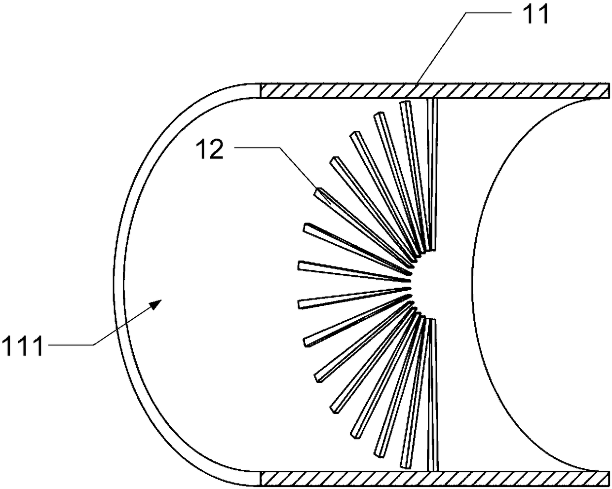
[0062] Please refer to Figure 6A and Figure 6B , in the first embodiment of the present application, the power part can be a piezoelectric ceramic vibrator 131, and the piezoelectric ceramic vibrator 131 has a plurality of them, and can be pasted on the outer surface of the body (pipe) 11 at equal intervals. , the water-repellent member 12 is a diaphragm 121 arranged on the inner surface of the flow guide channel 111, and the diaphragm 121 has certain toughness. Such as Figure 6A As shown, multiple sets of diaphragms 121 are arranged in the guide channel 111, and each set of diaphragms 121 is uniformly arranged on the inner surface of the pipe 11 in the axial direction, and each set of diaphragms 121 is also along the circumference of the inner surface of the pipe 11. Evenly distributed (such as Figure 6B As shown), each diaphragm 121 has the same inclination angle with the inner surface of the guide channel 111, preferably, the inclination angle can be set between 5° a...
Embodiment 2
[0065] see Figure 7 , in the second embodiment of the present application, the fluid drive device provided by the present invention is applied to the transportation of water bodies. The power element is a vibrator 132, and the vibrator 132 is, for example, a vibration motor, a pneumatic vibrator, a hydraulic vibrator, or a piezoelectric vibrator, but it is not limited thereto. The main body 11 is a trough-shaped container for water to flow, and the water-repelling member 12 is a diaphragm 122 with certain toughness. The vibrator 132 is fixed on the outer wall of the trough container 11, and the diaphragm 122 is evenly arranged on the inner wall of the trough container 11. The diaphragm 122 has a certain inclination angle with the inner wall of the tank-shaped container 111 , and the preferred inclination angle is between 5° and 89°. When the control unit 15 drives the vibrator 132 to vibrate, the vibrator 132 will drive the trough container 11 and the diaphragm 122 to vibra...
Embodiment 3
[0068] see Figure 8 , in the third embodiment of the present application, the power element is an electromagnetic coil 133 (which can also be designed as a permanent magnet), which can only be arranged at one end of the body 11, or can be arranged at both ends of the body 11 respectively , preferably, the axis of the electromagnetic coil 133 coincides with the axis of the guide channel 111 . The electromagnetic coil 133 can generate a magnetic field with variable strength. The water-repellent element 12 is a flexible magnetic film 123 containing magnetic material and arranged on the inner surface of the flow guide channel 111 . The magnetic film 123 is made of magnetic material or a composite material containing magnetic material. The magnetic material is a material capable of interacting with a magnetic field, including but not limited to ferrous materials, permanent magnetic materials, and soft magnetic materials. Preferably, the water-repelling element 12 is a diaphragm ...
PUM
 Abstract
Description
Claims
Application Information