
Cropping machine used for artificial plush cloth
A technology of artificial plush and cutting machine, which is applied in the cutting of textile materials, textiles and papermaking, etc. It can solve the problems of manpower consumption, poor efficiency, and unfavorable smooth progress, and achieve the effect of high work efficiency
- Summary
- Abstract
- Description
- Claims
- Application Information
AI Technical Summary
Problems solved by technology
Method used
Image

Examples
Embodiment Construction
[0026] In order to make the technical means, creative features, goals and effects achieved by the present invention easy to understand, the present invention will be further elaborated below in conjunction with illustrations and specific embodiments.
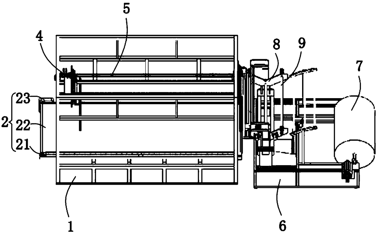
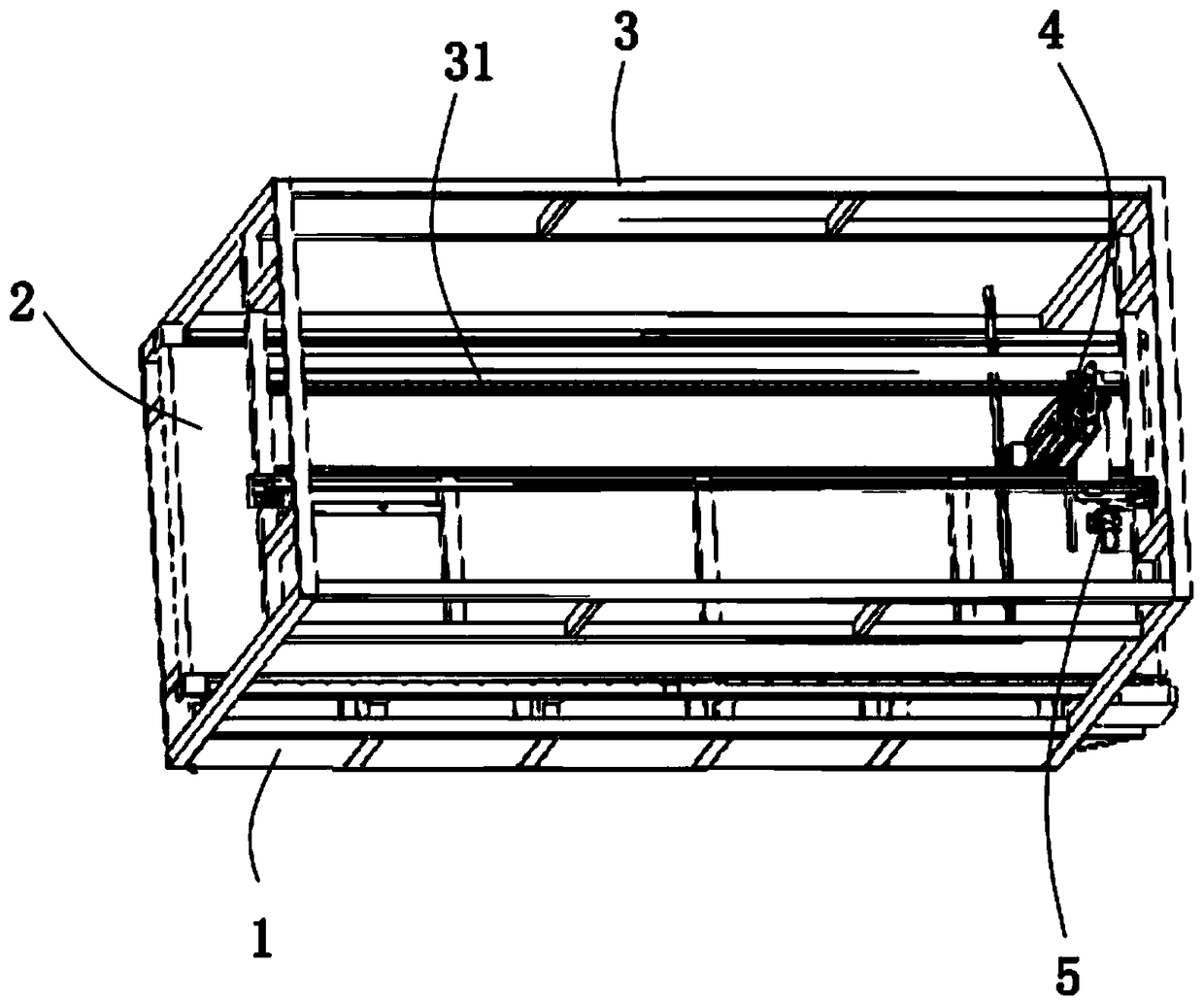
[0027] refer to figure 1 , figure 2 , image 3 , Figure 4 , Figure 5 , Image 6 As shown, the cutting machine for artificial plush cloth includes a first support platform 1, and a conveying mechanism 2 is fixed on the top surface of the first support platform 1;
[0028] The top of the first support platform 1 is fixed with a first fixed frame 3, and the inside of the first fixed frame 3 is symmetrically fixed with a first slide bar 31;
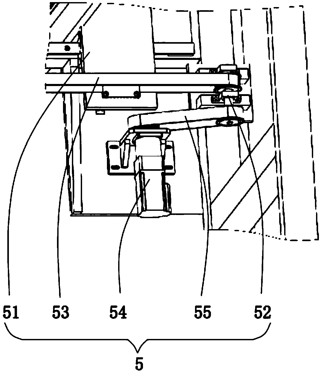
[0029] The inside of the first fixed frame 3 is provided with a transmission mechanism 5, and the transmission mechanism 5 includes a second fixed plate 51, a second rotating shaft 52, a second chain 53, a third rotating motor 54 and a third chain 55. The second fixing plate 51 is slid...
PUM
 Abstract
Description
Claims
Application Information