Motor and control method thereof

A technology of electromagnets and shells, applied in the direction of controlling mechanical energy, electrical components, electromechanical devices, etc., can solve the problem that the motor cannot drive the load to run, and achieve the effects of guaranteed performance, improved stability, and fast heat dissipation

Active Publication Date: 2019-04-09
浙江江宇电机有限公司
View PDF5 Cites 0 Cited by
  • Summary
  • Abstract
  • Description
  • Claims
  • Application Information

AI Technical Summary

Problems solved by technology

If the rotor of the motor is seriously shifted, the motor cannot drive the load to run at all.

Method used


Image

  • Motor and control method thereof
  • Motor and control method thereof
  • Motor and control method thereof

Examples


Embodiment Construction

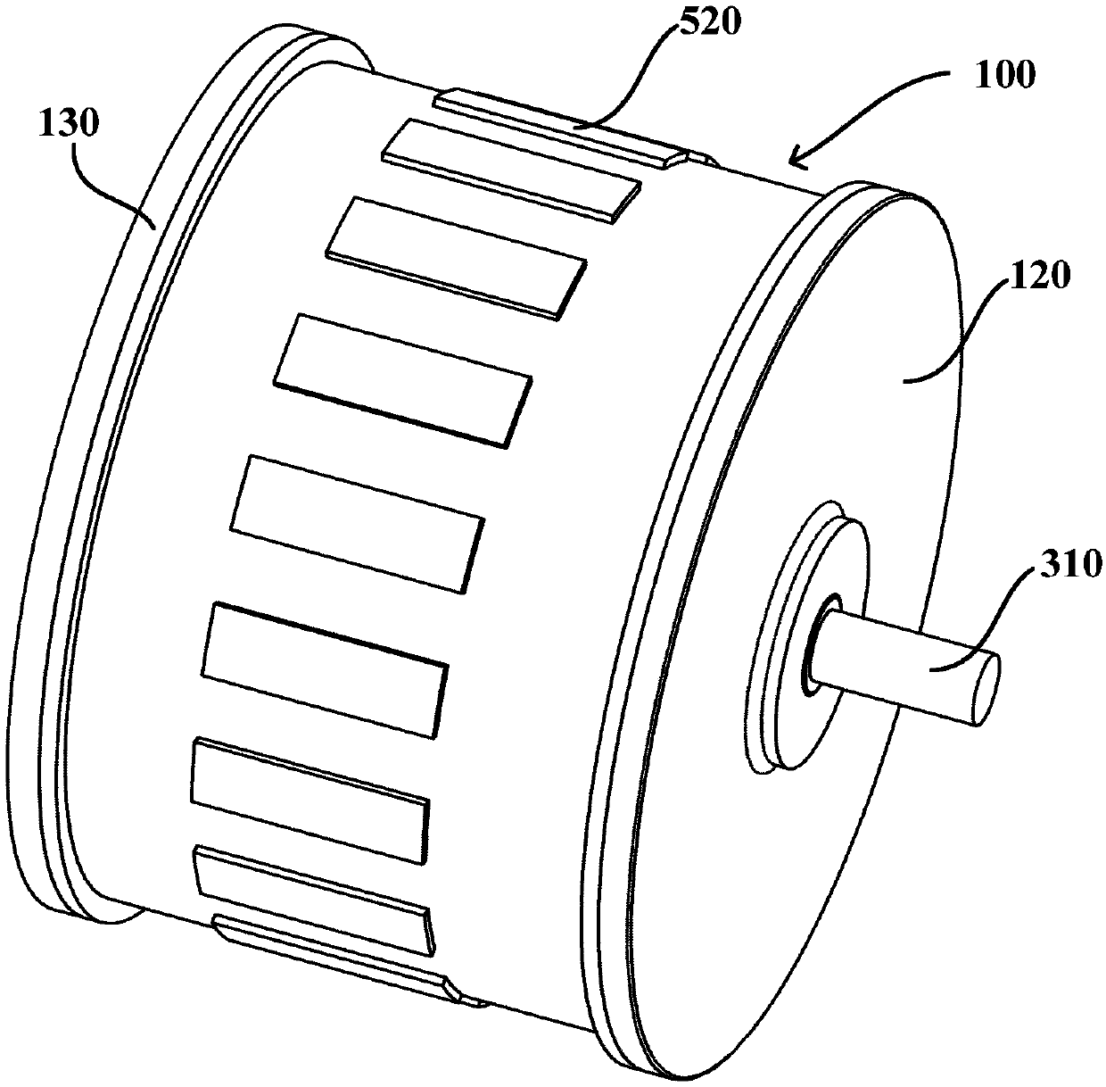
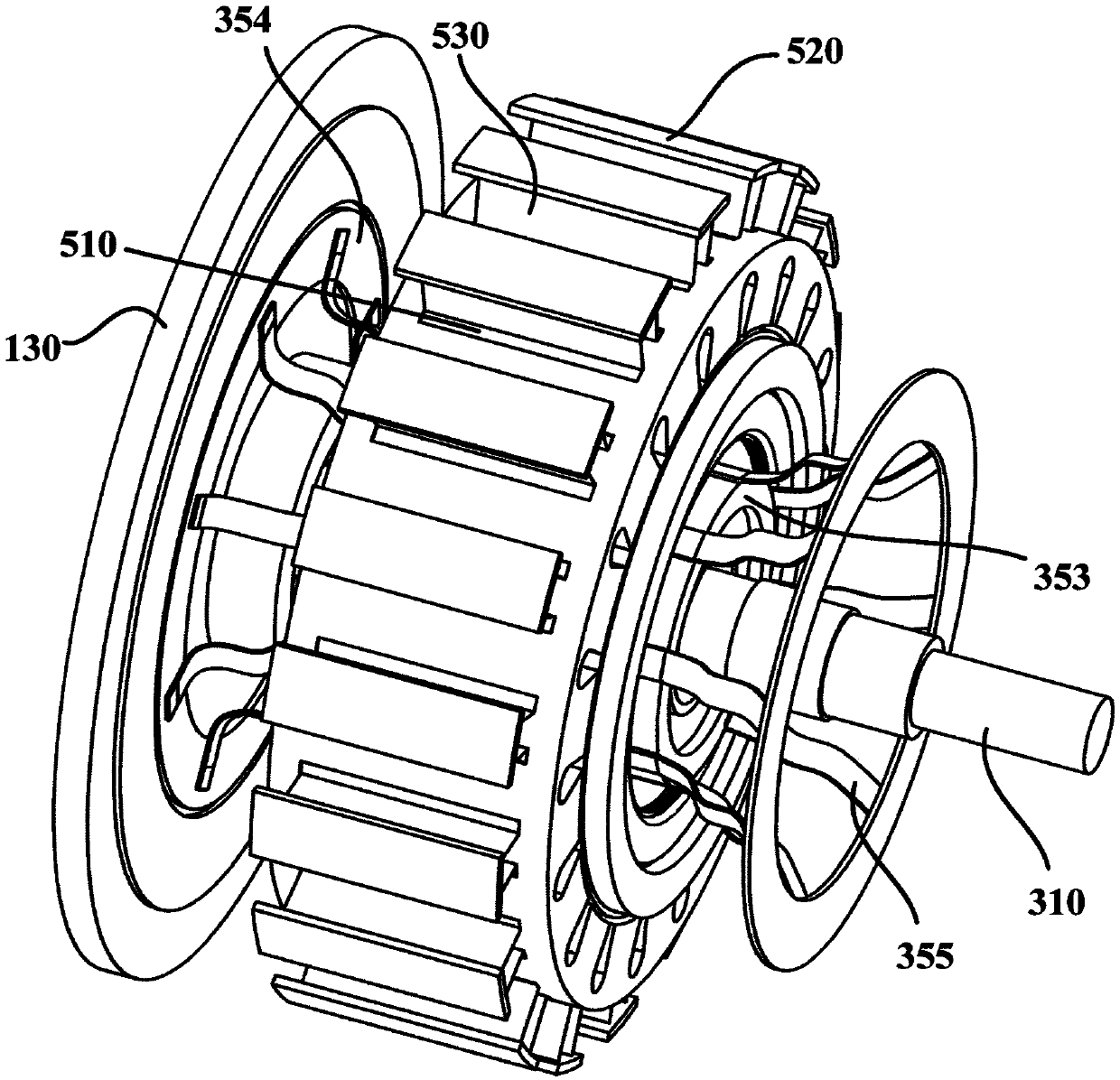
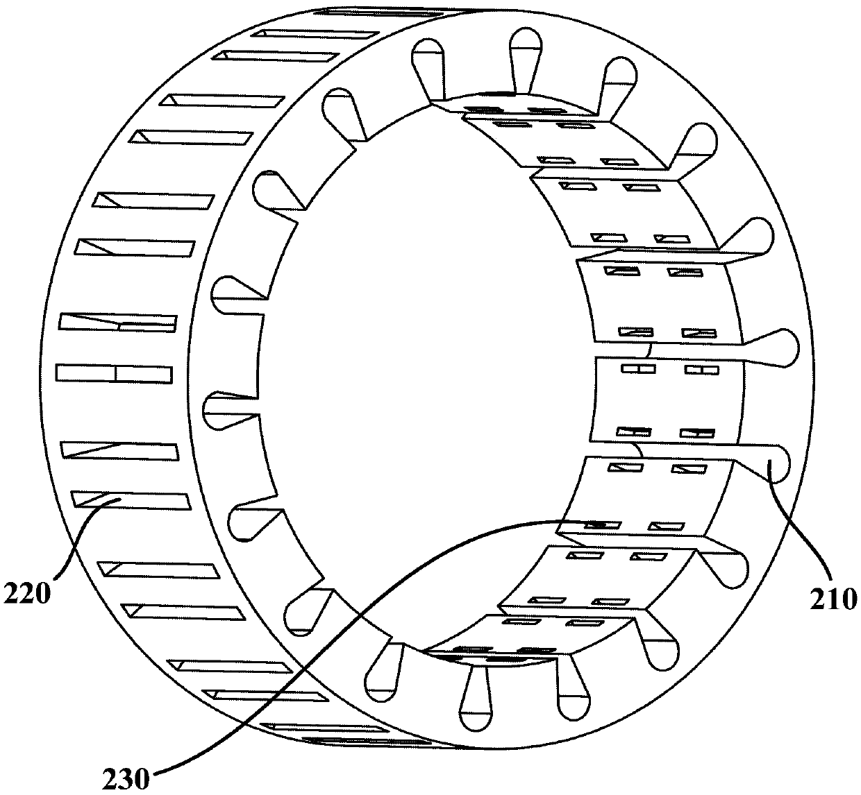
[0048] figure 1 is a schematic structural diagram of a motor according to an embodiment of the present invention. Such as figure 1 shown, and refer to Figure 2 to Figure 12 , the embodiment of the present invention provides a motor. Generally, the motor may include a housing 100 , a stator 200 and a rotor 300 . The housing 100 generally has a main housing 110 and end covers disposed on two ends of the main housing 110 , such as a housing front cover 120 and a housing rear end cover 130 . The stator 200 is disposed in the housing 100 . The rotor 300 is disposed radially inside the stator 200 . The iron core of the stator 200 has stator slots 210 for winding windings 240 .

[0049]In some embodiments of the present invention, in order to improve the heat dissipation performance of the motor, the stator 200 also has a plurality of cooling hole groups, and each cooling hole group has two first strip-shaped holes 220 arranged on both sides of a corresponding stator slot 210 ...


PUM


Abstract

The invention provides a motor and a control method thereof. The motor comprises a shell, a stator and a rotor, wherein the stator is arranged in the shell, the rotor is arranged at a radial inner side of the stator, the shell is provided with a rear end cover, a shaft end groove is formed in the rear end cover, the rotor is provided with an output shaft, a rear end of the output shaft is insertedinto the shaft end groove, the motor also comprises a play-prevention device and a play detection device, the play-prevention device is provided with an electromagnet and a permanent magnet, the electromagnet is arranged at the bottom of the shaft end groove, the permanent magnet is arranged at a rear end of the output shaft, and the play detection device is configured to detect displacement between a real-time position and an initial position of the output shaft and control the size and the direction of a current of the electromagnet according to the displacement so as to further control thesize of an acting force between the electromagnet and the permanent magnet and maintain the output shaft at the initial position. When axial display occurs in the output shaft, the current supplied to the electromagnet is controlled, the permanent magnet is pushed to drive the output shaft to move towards an opposite direction of an axial play direction, axial play is generated, and the rotationof the output shaft cannot be affected.

Description

technical field [0001] The invention relates to the field of motors, in particular to a motor and a control method thereof. Background technique [0002] At present, during the use of the motor, there is a special phenomenon that the rotor is shifting. The rotor of the motor breaks out of the stator core, and the axial displacement occurs, which is called the rotor drifting shaft. Normally, the ends of the stator core and rotor core are aligned, or the rotor is slightly shorter than the stator core. When the rotor core protrudes out of the stator core by 5 mm or more, the three-phase no-load current of the motor will increase significantly. After the load is applied, the stator current will exceed the rated current value, causing the motor to overheat. At the same time, there will be bursts of uneven but regular humming. If the motor rotor is severely shifted, the motor cannot drive the load to run at all. Contents of the invention [0003] The purpose of the present i...

Claims


Application Information

Patent Timeline
Patent Type & Authority Applications(China)
IPC IPC(8): H02K11/21H02K5/173H02K5/24H02K1/20H02K5/20H02K5/18H02K1/16H02K7/00
CPCH02K1/165H02K1/20H02K5/1732H02K5/18H02K5/20H02K5/24H02K7/003H02K11/21
Inventor 尹洁林金源李晓宇王银萍
Owner 浙江江宇电机有限公司
Why Eureka
Try Eureka