A thermally conductive film rewinding device

A heat-conducting film and unwinding device technology, which is applied in the direction of winding strips, transportation and packaging, thin material processing, etc., can solve problems such as uneven winding, affecting work efficiency, loose film tape, etc., and achieves simple and efficient design. Flexible and convenient edge-aligned roll-out effect

Active Publication Date: 2021-04-13
安徽长正升科技有限公司
View PDF5 Cites 0 Cited by
  • Summary
  • Abstract
  • Description
  • Claims
  • Application Information

AI Technical Summary

Problems solved by technology

[0003] There are certain disadvantages in the use of an existing heat-conducting film rewinding device. First, the film cannot be tightly attached to the film due to the loose film tape when winding the film. At the same time, it will The deviation of the film edge will cause uneven winding. After the work is finished, due to the inertia brought by the rotation of the shaft body, it will continue to rotate and release more heat-conducting film, which will affect the work efficiency.

Method used


Image

  • A thermally conductive film rewinding device
  • A thermally conductive film rewinding device
  • A thermally conductive film rewinding device

Examples


Embodiment 1

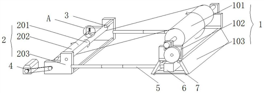
[0027] Such as Figure 1-5 As shown, a thermally conductive film rewinding device includes an unwinding device 1 and a winding device 2. The unwinding device 1 includes an unwinding shaft 101, a first support frame 102 and a base 103. Bearings are provided at both ends of the unwinding shaft 101. plate 12, and the bearing plate 12 is fixed on the top of the first support frame 102 by screws, the bottom end of the first support frame 102 is welded with a base 103, and the winding device 2 includes a first rolling shaft 201, a winding shaft 202 and a second support The frame 203, the first rolling shaft 201 and the winding shaft 202 are arranged up and down in the second supporting frame 203 in a staggered manner, and the inside of the second supporting frame 203 is located above the first rolling shaft 201. The end is connected with the motor 4 by a belt, and the two ends of the base 103 are equipped with a cylinder 6, and the cylinder 6 is connected with the second support fra...

Embodiment 2

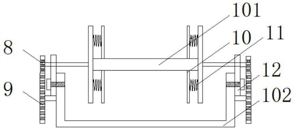
[0032] Such as Figure 1-5 The unwinding shaft 101 is welded with the first gear 8 at the part where the unwinding shaft 101 extends out of the bearing plate 12. Both sides of the first support frame 102 are connected with the second gear 9 through the resistance rotating shaft. The diameter of the first gear 8 is 5 cm, and the second gear 9 The diameter is 10cm, and the first gear 8 and the second gear 9 are engaged with each other.

[0033] The first gear 8 and the second gear 9 are set. After the motor 4 stops working, due to inertia, the unwinding 101 will continue to rotate. At this time, the first gear 8 drives the second gear 9 to rotate without external power. The friction between them and the resistance of the resistance rotating shaft offset the inertial force brought, thereby preventing the unwinding shaft 101 from continuing to rotate.

Embodiment 3

[0035] Such as Figure 1-5 As shown, the cross-sections of the unwinding shaft 101, the first rolling shaft 201 and the winding shaft 202 are all I-shaped, and the inner sides of the two ends of the unwinding shaft 101 are connected to the limit collar 10 by evenly setting 8 sets of first springs 11, which are I-shaped. The structure ensures that the thermal conductive film is neatly wrapped in each axis, thereby avoiding winding deviation to a certain extent;

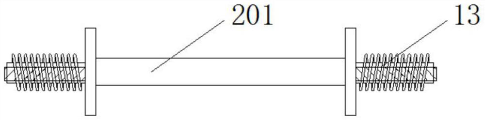
[0036] The first rolling shaft 201 is erected in the second support frame 203, and the two ends of the first rolling shaft 201 are sleeved with elastic sleeves 13. When the first rolling shaft 201 rotates, the elastic sleeve 13 is on the axis of the first rolling shaft 201. Fixed and rotated, the elastic sleeve 13 is in contact with the second support frame 203, which does not affect its rotation. The first rolling shaft 201 rotates on the surface of its axis. The spring sleeve 13 is elastically deformed to deal with ...


PUM


Abstract

The invention discloses a heat conduction film rewinding device, an unwinding device and a rewinding device. The unwinding device includes an unwinding shaft, a first support frame and a base. Bearing plates are provided at both ends of the unwinding shaft. The bearing plate is fixed on the top of the first support frame by screws, the bottom end of the first support frame is welded with a base, and the winding device includes a first rolling shaft, a winding shaft and a second support frame. Components, the built-in second rolling shaft is attached to the rolled-up heat-conducting film, and at the same time it is limited, so that each layer of the rolled-up film can be tightly attached together to prevent it from loosening and unfolding. The design is simple, Convenient and practical, the present invention sets the first gear and the second gear. After the motor stops working, the unwinding shaft will continue to rotate due to inertia. At this time, the first gear drives the second gear to rotate without external power. The resistance of the friction and resistance rotating shaft offsets the inertial force brought, thereby avoiding the continuous rotation of the unwinding shaft.

Description

technical field [0001] The invention relates to the field of heat conduction films, in particular to a heat conduction film rewinding device. Background technique [0002] Thermally conductive graphite film is also known as thermally conductive graphite sheet, heat-dissipating graphite film, graphite heat-dissipating film, etc. Thermally conductive graphite film is a new type of heat-conducting and heat-dissipating material. Its heat-conducting and heat-dissipating effect is very obvious, and it has been widely used in PDP , LCDTV, Notebook PC, UMPC, Flat Panel Display, MPU, Projector, Power Supply, LED and other electronic products. It is also one of the popular mobile phone heat dissipation films. Rewinding devices are often used in heat conduction film processing. [0003] There are certain disadvantages in the use of an existing heat-conducting film rewinding device. First, the film cannot be tightly attached to the film due to the loose film tape when winding the film. ...

Claims


Application Information

Patent Timeline
Patent Type & Authority Patents(China)
IPC IPC(8): B65H18/02B65H18/10B65H18/26B65H16/10B65H23/02B65H23/032
CPCB65H16/106B65H18/028B65H18/103B65H18/26B65H23/0216B65H23/032B65H2701/1133
Inventor 凌德根徐华容于海涛
Owner 安徽长正升科技有限公司
Why Eureka
Try Eureka