Novel wiper rubber strip anti-releasing structure and wiper thereof

An anti-detachment structure and adhesive strip technology, which is applied in the field of traffic safety, can solve problems such as increased costs, unsightly wiper structure, and stripped strips

Active Publication Date: 2019-05-24
XIAMEN FUKE CAR ACCESSORIES
View PDF9 Cites 7 Cited by
  • Summary
  • Abstract
  • Description
  • Claims
  • Application Information

AI Technical Summary

Problems solved by technology

[0003] The commonly used wiper is mainly composed of a spring piece, a rubber strip, a wiper joint, and a diversion sleeve. The rubber strip is clamped on the spring piece through the gap in the middle of the spring piece, because the rubber strip needs to push the spring piece from one end of the spring piece In daily use, there is a large contact force between the wiper and the window, and various wind and rain erosion during driving, making the rubber strip easily exposed from the end of the wiper spring. Cause the rubber strip to fall off. For this reason, someone on the market has designed a structure to prevent the rubber strip from falling off. The method is as follows figure 1 As shown, the end buckle 1' is set at both ends of the wiper to seal the tw

Method used


Image

  • Novel wiper rubber strip anti-releasing structure and wiper thereof
  • Novel wiper rubber strip anti-releasing structure and wiper thereof
  • Novel wiper rubber strip anti-releasing structure and wiper thereof

Examples


Embodiment 1

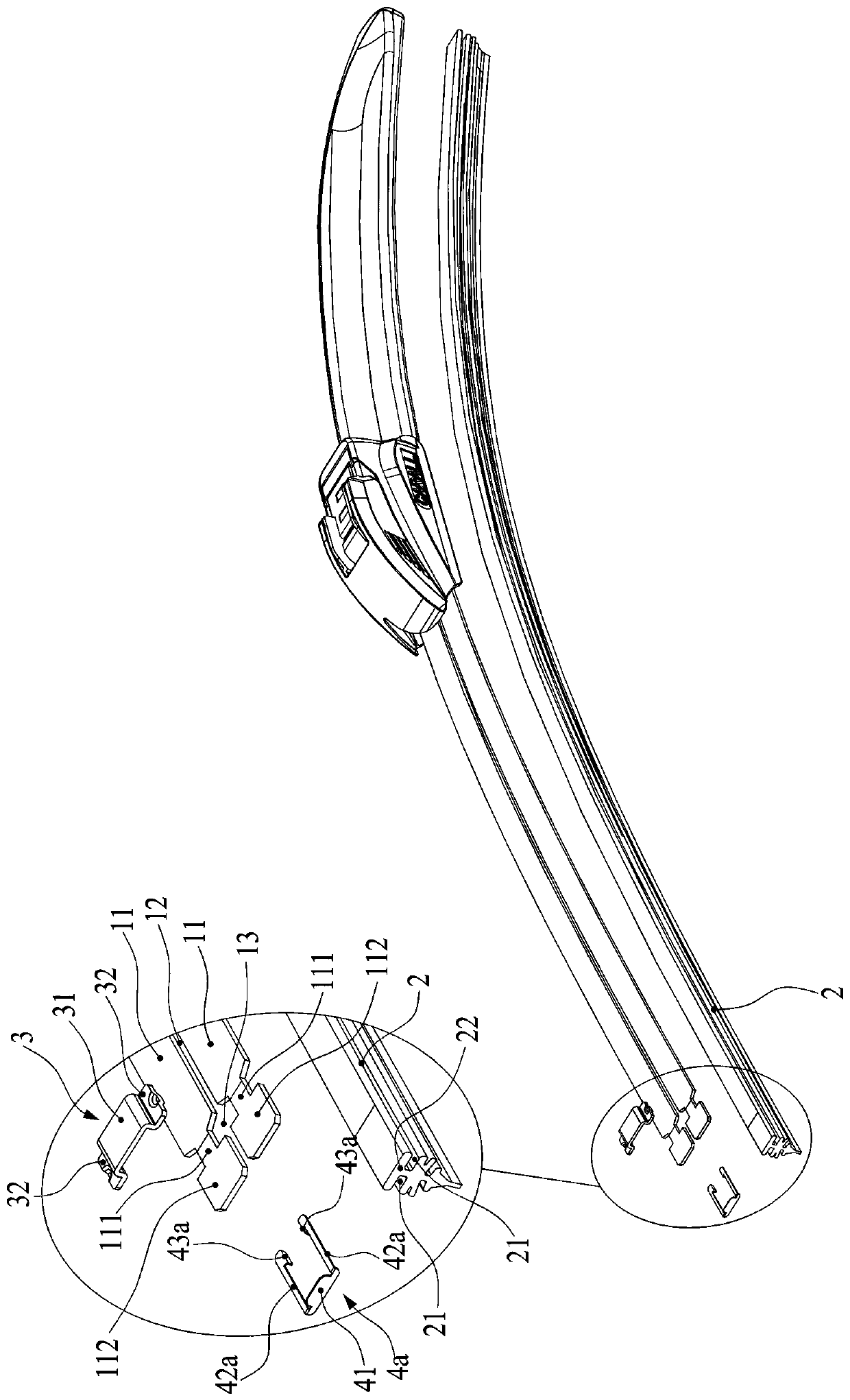
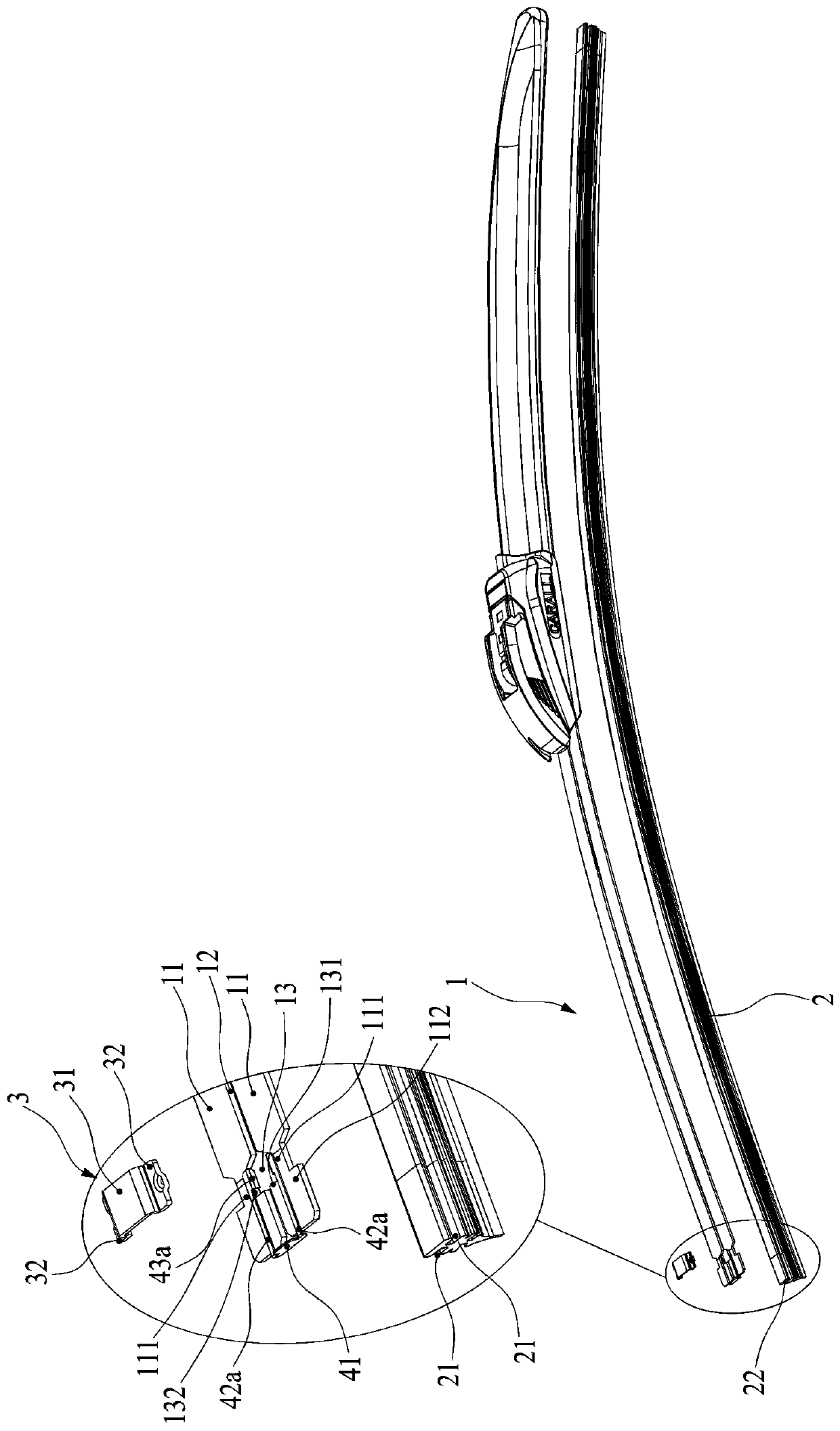
[0047] Such as Figure 2-Figure 5As shown, a new type of wiper rubber strip anti-off structure includes a spring piece 1 and a rubber strip 2. The spring piece 1 is composed of two spring pieces 11 arranged at intervals on the left and right. The two spring pieces 11 are adjacent to each other. The two ends 112 are respectively connected by a connecting piece 3. The middle of the connecting piece 3 is a flat plate 31, and each end is provided with a rest portion 32, which is in the shape of a boss as a whole. The two rest portions 32 are respectively welded to the phases of the two spring segments 11 On the adjacent two ends 112, a through cavity 33 is formed between the connecting piece 3 and the two spring segments 11; a gap 12 is formed in the middle of the two spring segments 11, and the left and right sides of the rubber strip 2 along the length direction Each has a slot 21 for inserting the spring pieces 11, the rubber strip 2 is pushed into the gap 12 between the spring...

Embodiment 2

[0052] The embodiment of the wiper rubber strip anti-off structure is basically the same as the structure of the first embodiment, except that there is a difference in the structure of the rubber strip plug. Therefore, the matching relationship between the rubber strip 2 and the spring piece 11 is that the connecting piece 3 and the The connection mode between the spring segments 11 refers to the description of the first embodiment, and will not be repeated. It should be noted that the two ends of the two spring segments 11 do not need to form the flared portion 13, that is, the flared portion 13 can be eliminated. However, if there is a flaring portion 13, it is convenient for the rubber strip 2 to pass through the gap 12 formed between the spring pieces 11. Such as Figure 6-Figure 8 As shown, the connector 42a of the strip plug 4b is a flat connecting arm 42a, and the two connecting arms 42a are closely attached to the top end surfaces of the two spring segments 11, which a...

Embodiment 3

[0056] The embodiment of the wiper rubber strip anti-off structure is basically the same as the structure of the first embodiment, except that there is a difference in the structure of the rubber strip plug. Therefore, the matching relationship between the rubber strip 2 and the spring piece 11 is that the connecting piece 3 and the The connection mode between the spring segments 11 refers to the description of the first embodiment, and will not be repeated. It should be noted that the two ends of the two spring segments 11 do not need to form the flared portion 13, that is, the flared portion 13 can be eliminated. However, if there is a flaring portion 13, it is convenient for the rubber strip 2 to pass through the gap 12 formed between the spring pieces 11. Such as Figure 9-Figure 11 As shown, the connector 42b of the rubber strip plug 4c is a first connector 42b in the shape of a flat plate, the first connector 42b is perpendicular to the spring piece 11, and is located on...


PUM


Abstract

Disclosed are a novel wiper rubber strip anti-releasing structure and a wiper thereof. The novel wiper rubber strip anti-releasing structure comprises a spring piece, a rubber strip and at least one rubber strip plug, wherein the spring piece is composed of two spring piece units arranged at an interval on the left and the right, a clamping seam is formed between the two spring piece units, the neighboring ends of the two spring piece units are connected through connecting pieces, between each connecting piece and the corresponding two ends of the two spring piece units forms a through cavity;the left and the right of the rubber strip are respectively provided with an inserting slot for arranging the corresponding spring piece unit in a penetrating mode, and when the rubber strip is pushed from the cavity at one end into the clamping seam between the two spring piece units, the sides of the two spring piece units can be inserted into the inserting slots of the left and the right of the rubber strip respectively to clamp the rubber strip into the clamping seam; the outer end of the at least one rubber strip plug is provided with a retaining edge for plugging outside the corresponding cavity, the inner end of the rubber strip plug is provided with a hooking unit for preventing the rubber strip plug from being released from the cavity, the rubber strip can be inserted via the gapbetween the rubber strip and the cavity, and the end portion of the rubber strip can abut against the inner wall of the retaining edge. The novel wiper rubber strip anti-releasing structure is light,convenient, attractive in appearance, less prone to falling off and easy to mount and dismount.

Description

technical field [0001] The invention relates to the field of traffic safety, in particular to a novel wiper strip anti-detachment structure and the wiper. Background technique [0002] The wiper is a small but not negligible auto part. It can polish the windshield of the car and make the driver's sight clearer. It is clean and clear to ensure driving safety. [0003] The commonly used wiper is mainly composed of a spring piece, a rubber strip, a wiper joint, and a diversion sleeve. The rubber strip is clamped on the spring piece through the gap in the middle of the spring piece, because the rubber strip needs to push the spring piece from one end of the spring piece In daily use, there is a large contact force between the wiper and the window, and various wind and rain erosion during driving, making the rubber strip easily exposed from the end of the wiper spring. Cause the rubber strip to fall off. For this reason, someone on the market has designed a structure to prevent...

Claims


Application Information

Patent Timeline
IPC IPC(8): B60S1/38
Inventor 王书屋
Owner XIAMEN FUKE CAR ACCESSORIES
Why Eureka
Try Eureka