Mechanical part grinding fixing device

A technology for fixing devices and mechanical parts, which is applied in the direction of grinding drive devices, grinding machine parts, grinding machines, etc. It can solve the problems of difficult polishing, inaccurate fixing and positioning of round tube parts, and parts that do not meet production requirements. Achieve convenient and effective polishing and polishing

Active Publication Date: 2019-07-12
CHANGZHOU INST OF MECHATRONIC TECH
View PDF5 Cites 29 Cited by
  • Summary
  • Abstract
  • Description
  • Claims
  • Application Information

AI Technical Summary

Problems solved by technology

[0003] 1. The fixed positioning of the round tube parts is not accurate, and the round tube parts are easy to rotate eccentrically during polishing and grinding, resulting in the processed parts not meeting the production requirements;
[0004] 2. There are various calibers of round tube parts, and it is more difficult to polish the inner wall of round tube parts with smaller caliber and longer length;
[0005] 3. The outer wall and inner wall of round tube parts cannot be polished at the same time. It needs to be processed in two processes, which affects the processing efficiency

Method used


Image

  • Mechanical part grinding fixing device
  • Mechanical part grinding fixing device
  • Mechanical part grinding fixing device

Examples


Embodiment 1

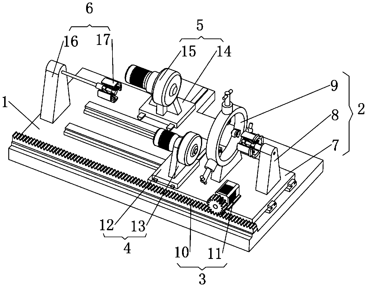
[0038] The present invention provides such Figure 1-7 A grinding and fixing device for mechanical parts shown includes a base 1, a fixing device 2, an axial driving unit 3, a rotating driving unit 4, an outer wall polishing unit 5 and an inner wall polishing unit 6, and the fixing device 2 includes a fixing device base 7, Inner wall fixing device 8 and outer wall limiting device 9.

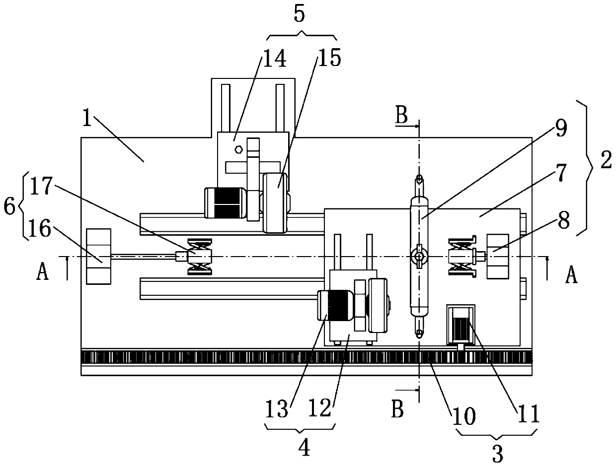
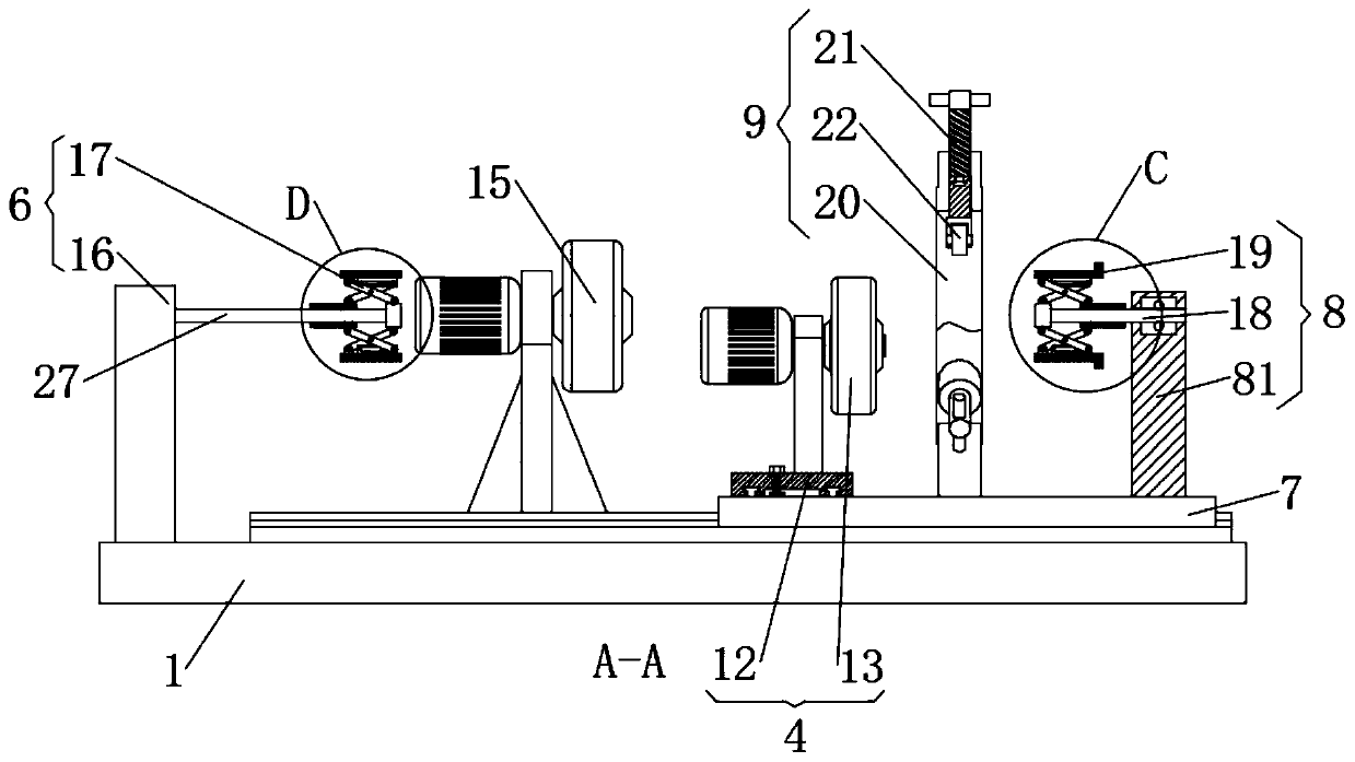
[0039] combine figure 1 and figure 2 As shown, the upper surface of the abutment 1 is provided with two slide rails 1 extending left and right in the length direction, and the bottom of the fixing device base 7 is slidably connected with the two slide rails 1. figure 2 and image 3 As shown, the right side of the upper surface of the fixing device base 7 is provided with an inner wall fixing device 8, the inner wall fixing device 8 is composed of a fixing device supporting column 81, an inner wall fixing screw 18 and an inner wall fixing head 19, and the bottom of the fixing device supportin...

Embodiment 2

[0043] The difference with embodiment 1 is:

[0044] combine image 3 and Figure 6 As shown, the middle part of the upper surface of the fixing device base 7 is provided with an outer wall limiting device 9, and the outer wall limiting device 9 includes an outer wall limiting ring seat 20, an outer wall limiting rod 21 and a runner 22, and the outer wall limiting ring seat 20 is circular. ring body, and the outer wall limit ring seat 20 is welded to the upper surface of the fixture base 7 by the bracket, and the outer wall limit ring seat 20 is connected with three outer wall limit rods 21, such as Figure 7 , the outer wall limit rod 21 is composed of a screw part and a limit rod part, the lower end of the screw part of the outer wall limit rod 21 is a "convex" type connection end, and the "convex" type connection end of the lower end of the outer wall limit rod 21 screw part is connected to the limit The upper end of the position rod part is rotationally connected, and th...


PUM


Abstract

The invention discloses a mechanical part grinding fixing device, and relates to the field of mechanical part machining equipment. The mechanical part grinding fixing device comprises a base platform,a fixing device, an axial driving unit, a rotatable driving unit, an outer wall polishing unit and an inner wall polishing unit; the fixing device comprises a fixing device base, an inner wall fixingdevice and an outer wall limiting device; the axial driving unit comprises a rack and a servo motor; the outer wall polishing unit is arranged on the back side of the left portion of the upper surface of the base platform; and the inner wall polishing unit is arranged on the left side of the upper surface of the base platform. According to the mechanical part grinding fixing device, the fixing device base is driven by the axial driving unit to move to uniformly grind the outer wall of a round pipe type part by cooperating with the outer wall polishing unit, and meanwhile an inner wall polishing head in the inner wall polishing unit goes deep into the inner wall of the round pipe type part to grind the inner wall of the round pipe type part.

Description

technical field [0001] The invention relates to the field of mechanical parts processing equipment, in particular to a grinding and fixing device for mechanical parts. Background technique [0002] In some mechanical processing production, it is necessary to grind the outer or inner wall of some round tube parts to increase the inner diameter or reduce the outer diameter of the round tube parts. The latter removes the rust spots on the inner and outer walls of the round tube parts to To meet the conditions of use, it is necessary to use pipe clamps to clamp and fix the round pipe parts, and then use polishing and grinding equipment to polish the round pipe parts. Common round tube parts are easy to encounter the following disadvantages when processing: [0003] 1. The fixed positioning of the round tube parts is not accurate, and the round tube parts are easy to rotate eccentrically during polishing and grinding, resulting in the processed parts not meeting the production r...

Claims


Application Information

Patent Timeline
Patent Type & Authority Applications(China)
IPC IPC(8): B24B5/12B24B27/00B24B29/08B24B41/06B24B47/12B24B47/20B24B47/22
CPCB24B5/12B24B27/0076B24B29/08B24B41/062B24B41/067B24B47/12B24B47/20B24B47/22
Inventor 于华艳刘江虞文武万文龙
Owner CHANGZHOU INST OF MECHATRONIC TECH
Why Eureka
Try Eureka