PCB connecting plate welding fixture for charger production

A welding fixture and charger technology, which is applied in welding equipment, auxiliary welding equipment, welding/cutting auxiliary equipment, etc., can solve the problems of poor use effect and large space occupied by students, and achieve improved anti-skid ability, good cushioning performance, smooth transition effect

Inactive Publication Date: 2019-08-09
YUEXI SWAN ELECTRONICS TECH
View PDF7 Cites 7 Cited by
  • Summary
  • Abstract
  • Description
  • Claims
  • Application Information

AI Technical Summary

Problems solved by technology

[0004] The purpose of the present invention is to provide a PCB connecting plate welding fixture for charger production, so as to solve the problem that the storage of the knotting frame needs to occupy more space and the students’ use effect is poor.

Method used


Image

  • PCB connecting plate welding fixture for charger production
  • PCB connecting plate welding fixture for charger production
  • PCB connecting plate welding fixture for charger production

Examples


Embodiment 1

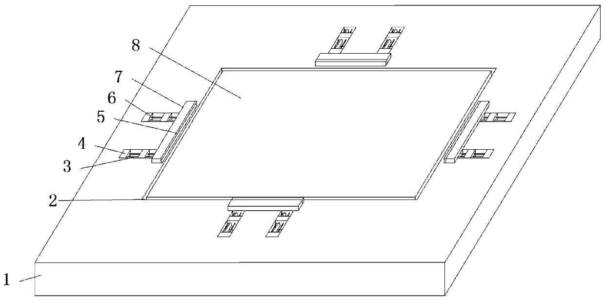
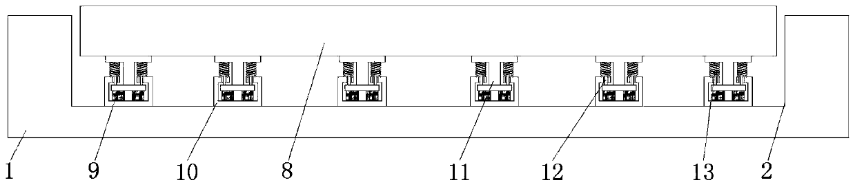
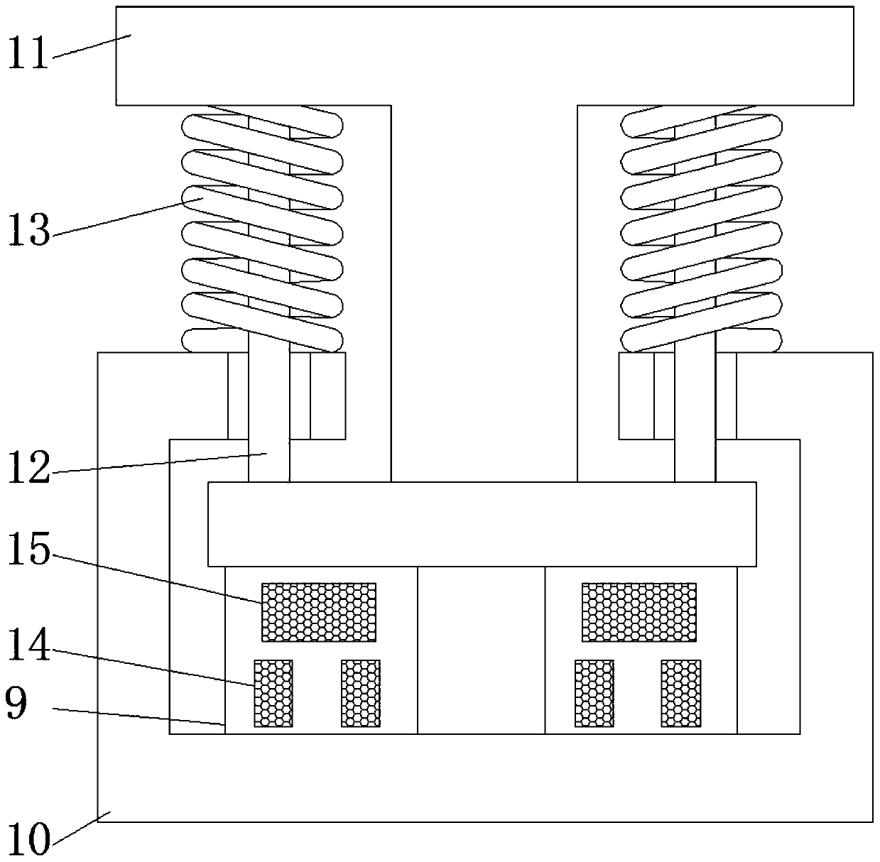
[0019] see Figure 1-3 , this embodiment provides a PCB connecting board welding fixture for charger production, including a base plate 1, a limiting groove 2 is provided in the center of the top of the base plate 1, a workbench 8 is arranged on the inner side of the limit groove 2, and the bottom of the workbench 8 Evenly arranged I-shaped blocks 11 are installed, and the inner side of the I-shaped block 11 is provided with a guide rod 12, the top of the guide rod 12 is nested with a spring 13, and the bottom end of the guide rod 12 runs through the chuck 10, and the chuck 10 The inner side is provided with two buffer columns 9, the interior of the buffer column 9 is provided with an upper cavity 15, and the lower cavity 14 is provided below the upper cavity 15, and the interiors of the lower cavity 14 and the upper cavity 15 are completely filled with rubber. Particles, the top of the buffer column 9 is fixedly installed with the I-shaped block 11, the outer edge of the limi...

Embodiment 2

[0022] see Figure 1-3 On the basis of Embodiment 1, a further improvement has been made: both sides of the top of the chuck 10 are provided with through holes, which are convenient for installation and clamping, and the through holes are inserted into the guide rod 12 to ensure the stability of the installation. The positioning block 7 There are four of them, and they are arranged opposite to each other, which improves the force uniformity of the PCB connecting board.

[0023] Wherein, one side of the rubber pad 5 is provided with a semi-circular groove, which is convenient for limit engagement on the side of the PCB connecting board and improves the clamping tightness.


PUM


Abstract

The invention discloses a PCB connecting plate welding fixture for charger production. The PCB connecting plate welding fixture comprises a baseplate. The top center of the baseplate is provided witha limiting groove. A workbench is arranged on the inner side of the limiting groove. Uniformly distributed H-shaped blocks are installed on the bottom of the workbench. A guide rod is arranged on theinner side of each H-shaped block. The top end of the guide rod is provided with a spring in a nested way. A chuck is arranged on the bottom end of the guide rod in a penetrating way. Two buffer postsare arranged on the inner side of the chuck. An upper cavity is arranged in each buffer post. The problem that the existing PCB connecting plate welding fixture generally performs direct clamping anddirectly uses the action force on that PCB connecting plate, the clamping pressure is high and the PCB connecting plate is liable to be extruded to deform; meanwhile, the existing PCB connecting plate welding fixture is directly placed on the workbench surface and does not have certain buffering capacity, and the PCB connecting plate is liable to be damaged by the force when the welding pressureis high.

Description

technical field [0001] The invention relates to the technical field of charger production, in particular to a PCB connecting plate welding jig for charger production. Background technique [0002] The charger adopts high-frequency power supply technology and uses advanced intelligent dynamic adjustment charging technology. The power frequency machine is designed based on the traditional analog circuit principle. The internal power components (such as transformers, inductors, capacitors, etc.) of the machine are relatively large. There is less noise when running with a large load, but this model has strong resistance to harsh grid environment conditions, and its reliability and stability are stronger than high-frequency machines. [0003] In the production process of the charger, the PCB connection board needs to be welded by resistance, and the fixture is needed in the welding process. The existing PCB connection board welding fixture is generally directly clamped, because t...

Claims


Application Information

Patent Timeline
Patent Type & Authority Applications(China)
IPC IPC(8): H05K13/00H05K3/34B23K37/04
CPCB23K37/04H05K3/34H05K13/0069
Inventor 储荣生
Owner YUEXI SWAN ELECTRONICS TECH
Why Eureka
Try Eureka