Method and Device for Controlling a Hydraulic Brake System

A technology of hydraulic braking and braking system, applied in braking safety system, braking action starting device, fluid pressure actuating device, etc., to achieve the effect of smoothing volume flow, saving cost and improving NVH characteristics

Active Publication Date: 2019-12-10
ROBERT BOSCH GMBH
View PDF7 Cites 0 Cited by
  • Summary
  • Abstract
  • Description
  • Claims
  • Application Information

AI Technical Summary

Problems solved by technology

The disadvantage is the cost of this damping measure, in addition, this throttle also creates an additional load on the motor and pump

Method used


Image

  • Method and Device for Controlling a Hydraulic Brake System
  • Method and Device for Controlling a Hydraulic Brake System
  • Method and Device for Controlling a Hydraulic Brake System

Examples


Embodiment Construction

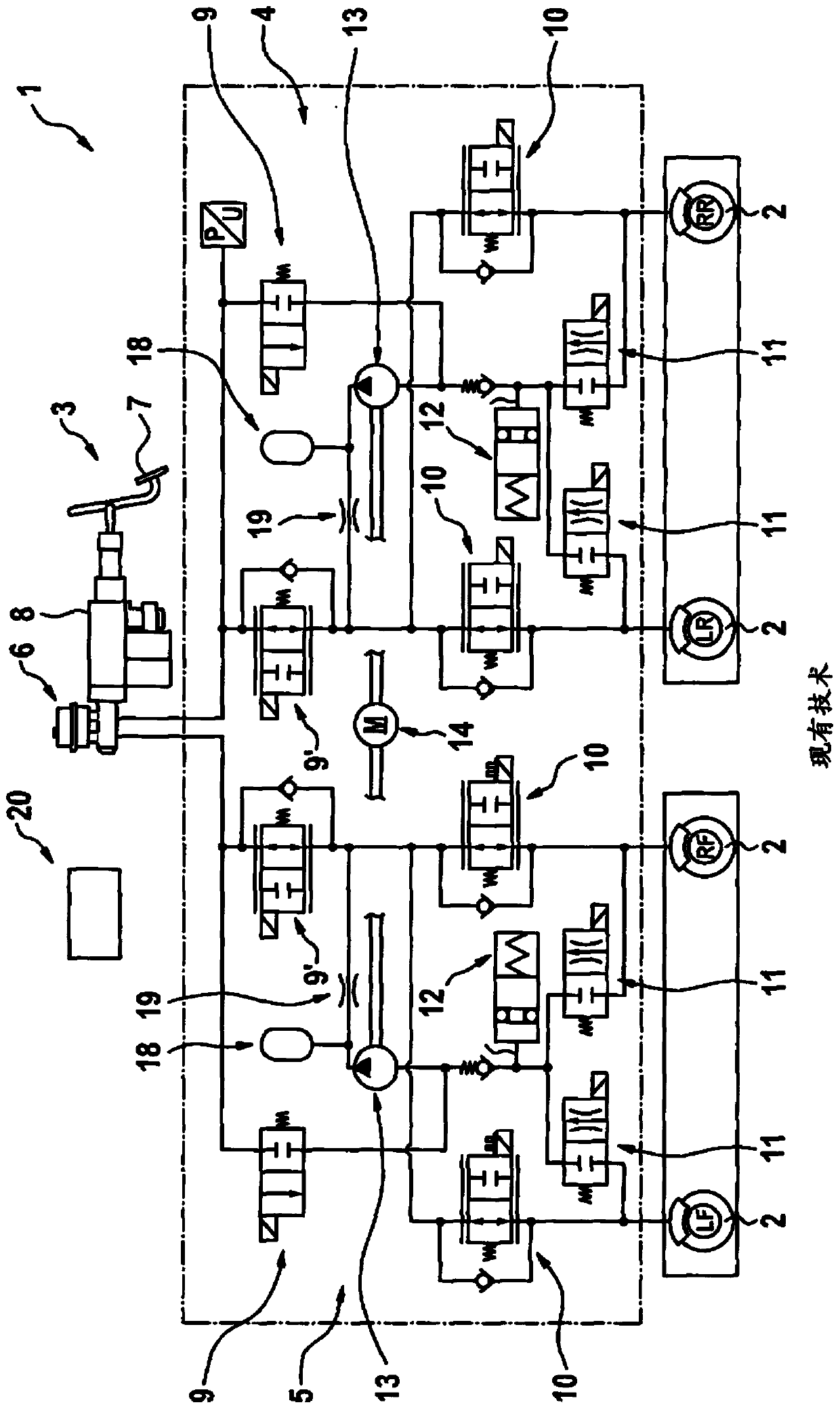
[0041] figure 1 A brake system 1 for a motor vehicle is shown in a simplified illustration, which is not shown in detail here. Brake system 1 has a plurality of wheel brakes 2 which, as service brakes, can be actuated by a driver of the motor vehicle by means of a brake pedal arrangement 3 . The wheel brakes 2 are represented by LR, RF, LF and RR, where their positions or corresponding relationships on the motor vehicle are specified, LR is the left rear, RF is the right front, LF is the left front, and RR is the right rear. Two brake circuits 4 and 5 are formed at brake pedal arrangement 3 and wheel brake 2 , brake circuit 4 being assigned to wheel brakes LF and RR and brake circuit 5 being assigned to wheel brakes LR and RF. The two brake circuits 4 and 5 are constructed identically, so that the structure of the two brake circuits 4 , 5 will be explained in more detail below with reference to the brake circuit 4 .

[0042] The brake circuit 4 is initially connected to the ...


PUM


Abstract

The present invention relates to a method for controlling a hydraulic brake system. The hydraulic brake system comprises a hydraulic pump which is driven by an electric motor and has the purpose of generating a fluid volume flow for the hydraulic brake system; and a solenoid valve for controlling the fluid volume flow from the hydraulic pump to a wheel brake, a method includes actuating the solenoid valve in such a way that by this means a fluid pulsation at the wheel brake is counteracted. Furthermore, the method may be implemented in a corresponding device.

Description

technical field [0001] The invention relates to a method for controlling a hydraulic braking system, wherein the braking system comprises a hydraulic pump driven by an electric motor for generating a fluid volume flow for the hydraulic braking system, and the braking system comprises a solenoid valve for The method is used for controlling the fluid volume flow from a hydraulic pump to the wheel brakes, wherein the method is characterized in that a solenoid valve is actuated in order to counteract fluid pulsations at the wheel brakes. Furthermore, the invention relates to a corresponding device. Background technique [0002] Driver assistance systems such as ESP require valves and pressure supply units to actively intervene in the pressure regulation at the wheel brake calipers. These valves are usually designed as solenoid valves, which are originally designed to regulate a predetermined pressure difference and therefore have very low hydraulic resistance. The most commonl...

Claims


Application Information

Patent Timeline
Patent Type & Authority Applications(China)
IPC IPC(8): B60T8/17F04B49/06
CPCB60T8/17F04B49/06B60T7/042B60T8/00B60T8/173B60T8/4068B60T8/4872B60T13/146B60T13/662B60T13/686B60T17/22B60T13/161B60T15/028F15B21/008
Inventor C·埃姆德H·德鲁克恩米勒H·库尔茨P·舍林格Y·纳夫鲁兹A·施密特莱因
Owner ROBERT BOSCH GMBH
Why Eureka
Try Eureka