A continuous heating stabilized water heater

A pressure-stabilized water heater, heating technology, applied in water heaters, fluid heaters, lighting and heating equipment, etc., can solve the problem of slow water temperature rise and achieve the effect of water pressure stability

Active Publication Date: 2021-07-13
山东康宅超净空气设备有限公司
View PDF9 Cites 0 Cited by
  • Summary
  • Abstract
  • Description
  • Claims
  • Application Information

AI Technical Summary

Problems solved by technology

[0005] The purpose of the present invention is to provide a continuous heating type water heater with stable water pressure and rapid increase in water temperature in order to solve the above problems that the water pressure in the water tank gradually decreases and the water temperature rises slowly

Method used


Image

  • A continuous heating stabilized water heater
  • A continuous heating stabilized water heater

Examples


Embodiment 1

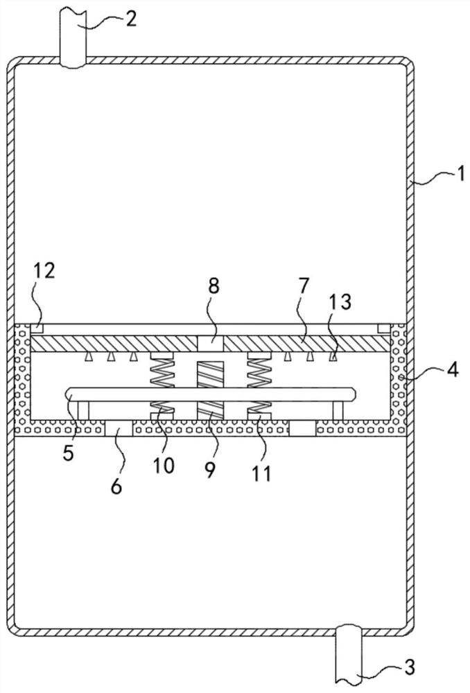
[0019] Such as figure 1 As shown, a continuous heating type water heater with constant pressure includes a box body 1, the upper end and the lower end of the box body 1 are fixedly connected with a water inlet pipe 2 and a water outlet pipe 3 respectively, and a heating tank 4 is sealed and slidably connected to the inner wall of the box body 1 , the density of the heating tank 4 is lower than that of water, and the inner bottom surface of the heating tank 4 is provided with a heating device 5. It should be noted that the heating device 5 is an annular heating tube, and the annular heating tube and the sealing column 9 are coaxially arranged, and the annular heating tube can quickly And uniformly heat up the water in the heating tank 4, the bottom surface of the heating tank 4 is provided with a through hole 6, and the inner side wall of the heating tank 4 is sealed and slidably connected with a heat shield 7. It should be noted that the inner side of the heating tank 4 The li...

Embodiment 2

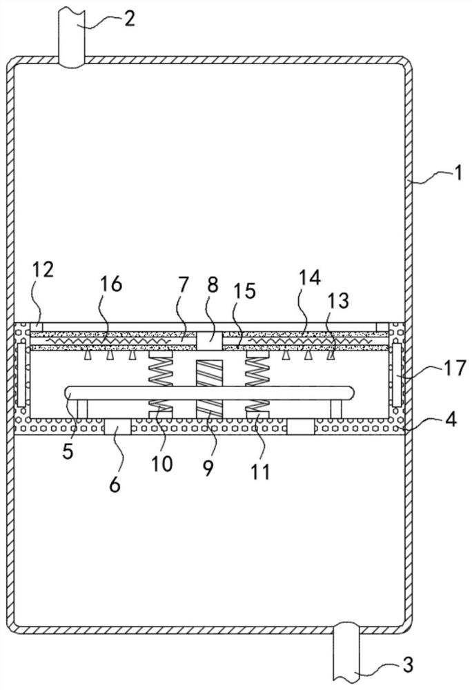
[0026] Such as figure 2 As shown, the difference between this embodiment and Embodiment 1 is that the heat insulation board 7 is composed of an upper heat preservation board 14 and a lower heat conduction board 15, and a closed heating coil 16 is arranged between the upper heat preservation board 14 and the lower heat conduction board 15, Two symmetrically arranged permanent magnet strips 17 are fixedly embedded on the inner side wall of the heating tank 4 , and the opposite sides of the two permanent magnet strips 17 have opposite magnetic poles.

[0027] In this embodiment, when the memory spring 10 pulls the heat shield 7 to move downward and rotate, it drives the two permanent magnetic strips 17 to rotate, and the magnetic flux in the closed heating coil 16 changes momentarily. It can be seen from the phenomenon of electromagnetic induction that the closed circuit When a part of the conductor moves to cut the magnetic induction line, a current will be generated on the con...


PUM


Abstract

The invention belongs to the field of household electrical appliances, and in particular relates to a continuous heating type stabilized water heater, which includes a box body. The upper end and the lower end of the box body are fixedly connected with a water inlet pipe and a water outlet pipe respectively, and the inside wall of the box body is sealed. A heating tank is slidingly connected, the density of the heating tank is lower than that of water, the inner bottom of the heating tank is provided with a heating device, the bottom of the heating tank is provided with a through hole, and the inner side wall of the heating tank is sealed and slidingly connected with a heat-insulating The heat insulation board is provided with a sealing hole, the inner bottom surface of the heating tank is fixedly connected with a sealing column, and the sealing column is set through the sealing hole, and the side walls of the sealing column and the sealing hole are provided with threads , the sealing column is threadedly connected with the heat shield. The invention can control the elongation or shortening of the memory spring by temperature, and then control the opening and closing of the sealing hole, so as to ensure the stability of the water pressure in the water tank, and can continuously and quickly provide hot water to users while ensuring the temperature of the hot water.

Description

technical field [0001] The invention belongs to the field of household electrical appliances, in particular to a continuous heating type constant pressure water heater. Background technique [0002] Compared with solar water heaters, electric water heaters have the advantages of simple installation, convenient use, and are not affected by the difference in air pressure between natural gas floors, and are increasingly becoming the first choice of users. [0003] When the existing electric water heater is used, with the consumption of hot water in the water tank, the water pressure in the water tank decreases, resulting in insufficient water output from the outlet pipe. In order to ensure the water pressure in the water tank, it is necessary to continuously replenish the water tank with cold water, and The mixed hot and cold water will bring a poor experience to the user. At the same time, the water temperature in the water tank will gradually decrease, and the power of the he...

Claims


Application Information

Patent Timeline
Patent Type & Authority Patents(China)
IPC IPC(8): F24H1/18F24H9/18F24H9/00
CPCF24H1/185F24H9/0005F24H9/1818
Inventor 刘峰刘守菊李宝营
Owner 山东康宅超净空气设备有限公司
Why Eureka
Try Eureka