A smart substation

A technology of intelligent substation and resistance

Inactive Publication Date: 2020-10-30
李海勇 +8
View PDF3 Cites 0 Cited by
  • Summary
  • Abstract
  • Description
  • Claims
  • Application Information

AI Technical Summary

Problems solved by technology

[0003] There are often some inductive loads on the user end, also known as inductive loads. Common inductive loads such as motors and circuits with coils basically have more or less inductive resistance. These inductive loads require electric energy to drive, although pure inductive loads , the current passing through it will not be consumed, its current is called reactive current in the circuit, and the power occupied in the grid is called reactive power, reactive power does not produce consumption, but from the perspective of the total grid, First, the reactive current will cause heat loss due to the need to be transmitted through cables. Second, after the reactive power occupies the grid, the grid cannot distribute this part of power to other places for use. On the whole, the actual use of the grid is reduced. Efficiency, therefore, most of the power consumers need to improve their own power factor as much as possible in order to occupy smaller resources in the grid
[0004] Reactive power compensation is an effective means to deal with reactive power occupation, but reactive power compensation needs to first know the power factor on the original circuit in order to perform compensation control. The complexity of power grid loads makes it difficult to calculate the power factor. How to detect power in real time Factor and corresponding compensation to make the total power factor tend to 1 is a big problem

Method used


Image

  • A smart substation
  • A smart substation
  • A smart substation

Examples


Embodiment Construction

[0039] The following will clearly and completely describe the technical solutions in the embodiments of the present invention with reference to the accompanying drawings in the embodiments of the present invention. Obviously, the described embodiments are only some, not all, embodiments of the present invention. Based on the embodiments of the present invention, all other embodiments obtained by persons of ordinary skill in the art without making creative efforts belong to the protection scope of the present invention.

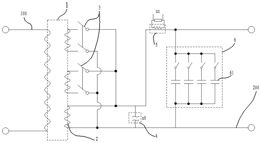
[0040] Such as figure 1 As shown, a smart substation includes a transformer 1. The transformer 1 includes a primary terminal and a secondary terminal 2. The primary terminal is connected to the mains terminal 100, and the secondary terminal 2 is connected to the user terminal 200. The smart substation also includes a capacitor bank 6. The capacitor bank 6 is arranged on the secondary terminal 2 , and the capacitor bank 6 and the user terminal 200 are connected...


PUM


Abstract

The invention discloses an intelligent substation. The intelligent substation comprises a transformer, the transformer comprises a primary end and a secondary end, the primary end is connected with amains supply end, the end part of the secondary end is connected with a user end, the intelligent substation further comprises a capacitor bank, the capacitor bank is arranged on the secondary end, and the capacitor bank is connected with the user end in parallel. The intelligent substation further comprises a power factor measurement module, the capacitor bank comprises a plurality of capacitorswhich are independent of one another and are connected in parallel, and the power factor measurement module acquires electric signals from the secondary ends and controls the number of the capacitorsconnected into the secondary end. Starting from the transformer substation, the total power factor of the secondary end is close to 1, and the power occupation of the external power grid of the mainssupply end is reduced; and when the capacitance is large and the single value is small, the step of power factor allocation can be reduced, and the stepless regulation effect can be achieved within acertain precision range.

Description

technical field [0001] The invention relates to the field of substations, in particular to an intelligent substation. Background technique [0002] The substation is an integral part of the power system. The substation can be a step-up station or a step-down station. The step-down station near the user end converts the high-voltage electricity in the grid into the low-voltage electricity used by the user end. 220V, 380V, etc. [0003] There are often some inductive loads on the user end, also known as inductive loads. Common inductive loads such as motors and circuits with coils basically have more or less inductive resistance. These inductive loads require electric energy to drive, although pure inductive loads , the current passing through it will not be consumed, its current is called reactive current in the circuit, and the power occupied in the grid is called reactive power, reactive power does not produce consumption, but from the perspective of the total grid, First...

Claims


Application Information

Patent Timeline
Patent Type & Authority Patents(China)
IPC IPC(8): H02J3/18
CPCH02J3/1864H02J3/1878Y02E40/30
Inventor 邹虚
Owner 李海勇
Why Eureka
Try Eureka