Bias voltage control method, bias voltage control device, modulator, and storage medium

A bias control and modulator technology, applied in the field of signal processing, can solve problems such as high computational complexity

A bias control and modulator technology, applied in the field of signal processing, can solve problems such as high computational complexity

CN110971306AActive Publication Date: 2020-04-07WUHAN OPTICAL VALLEY INFORMATION OPTOELECTRONICS INNOVATION CENT CO LTD +1

Image

  • Bias voltage control method, bias voltage control device, modulator, and storage medium
  • Bias voltage control method, bias voltage control device, modulator, and storage medium
  • Bias voltage control method, bias voltage control device, modulator, and storage medium

Examples


Embodiment Construction

[0067] The following will clearly and completely describe the technical solutions in the embodiments of the present invention with reference to the drawings in the embodiments of the present invention.

[0068] It should be understood that the specific embodiments described here are only used to explain the present invention, not to limit the present invention.

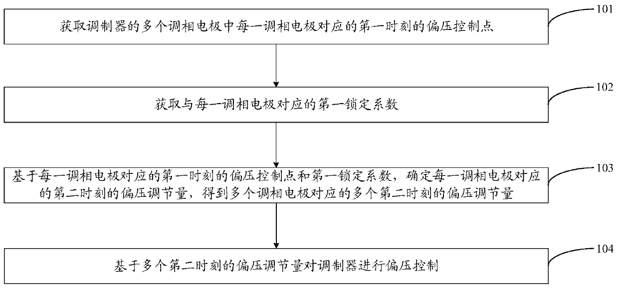
[0069] Embodiments of the present invention provide a bias control method, which is applied to a modulator, referring to figure 1 As shown, the method includes the following steps:

[0070] Step 101. Obtain a bias voltage control point at the first moment corresponding to each phase modulation electrode among the plurality of phase modulation electrodes of the modulator.

[0071] In an embodiment of the present invention, the modulator includes a plurality of phase-modulating electrodes. Here, an IQ modulator is taken as an example for illustration, and the IQ modulator includes a phase-modulating electrode I, a pha...


PUM


Abstract

The embodiment of the invention discloses a bias voltage control method. The method comprises the following steps: acquiring a bias voltage control point at a first moment corresponding to each phasemodulation electrode in a plurality of phase modulation electrodes of a modulator; obtaining a first locking coefficient corresponding to each phase modulation electrode; based on the bias voltage control point and the first locking coefficient of the first moment corresponding to each phase modulation electrode, determining the bias voltage adjustment amount of each phase modulation electrode corresponding to the second moment, and obtaining a plurality of bias voltage adjustment amounts of the plurality of phase modulation electrodes corresponding to the plurality of second moments; and performing bias control on the modulator based on the bias adjustment amounts at the plurality of first moments. The embodiment of the invention further discloses a bias control device, a modulator and astorage medium.

Description

technical field [0001] The invention relates to the field of signal processing, in particular to a bias voltage control method, a bias voltage control device, a modulator and a storage medium. Background technique [0002] At present, coherent optical communication technology is used for medium and long-span transmission. In coherent optical communication, in order to realize the control of the working bias voltage of the modulator, in the related art, a perturbation signal is generally applied to the phase modulation electrode of the modulator, and the amplitude of the output signal of the modulator is directly detected or the output optical power P out Perform frequency domain analysis to obtain the working bias; the above method is directly based on the Fourier transform of the output optical power P corresponding to the input signal out Frequency domain analysis is performed to obtain the working bias voltage; however, this way of calculating the working bias voltage ha...

Claims


Application Information

Patent Timeline
07 Apr 2020
Publication
CN110971306A
IPC
H04B10/548
CPC
H04B10/548
Inventors
胡蕾蕾; 陈宏刚