Tumor taking device for oncology

A tumor and negative pressure generator technology, applied in the medical field, can solve the problems of increased surgery, peripheral tissue damage, tumor clipping, etc., and achieves the effects of improving the success rate of surgery, reducing the difficulty of manufacturing, and improving work efficiency.

Inactive Publication Date: 2020-06-19
THE AFFILIATED HOSPITAL OF QINGDAO UNIV
View PDF12 Cites 2 Cited by
  • Summary
  • Abstract
  • Description
  • Claims
  • Application Information

AI Technical Summary

Problems solved by technology

[0003] When a surgeon performs an operation on a patient, the tumor is generally extracted with medical tweezers during tumor resection. However, when the tweezers are used to extract the tumor, there are only two stress points on the tumor and the force area is small. If it is too small, the tumor cannot be clamped. If the force is too large, it is easy to crush the tumor, which is very inconvenient, and sometimes even adds some unnecessary difficulties to the operation, because it is easy to destroy the tumor focus with hands or instruments , loses the original shape, which affects the surgeon's judgment of the pathological condition of the lesion from its appearance, and has a certain impact on the further diagnosis of the disease. During the operation, the opening is relatively small, and the tweezers are easy to touch the surrounding tissue and cause damage to the surrounding tissue. , and the process of tumor clipping will lead to tumor rupture. After the rupture, the incomplete tumor will have the risk of implantation and metastasis to other parts. There is no good clamping fixture to stably fix the tumor, which makes it necessary to do fine In the tumor resection operation, the accuracy of the operation is not high, and it takes a long time, so the innovation of the complete tumor removal tool is particularly important

Method used


Image

  • Tumor taking device for oncology
  • Tumor taking device for oncology
  • Tumor taking device for oncology

Examples


Embodiment Construction

[0030] Embodiments of the present invention will be further described in detail below in conjunction with the accompanying drawings.

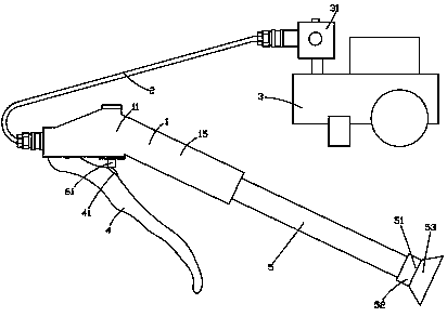
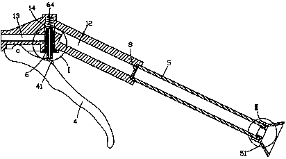
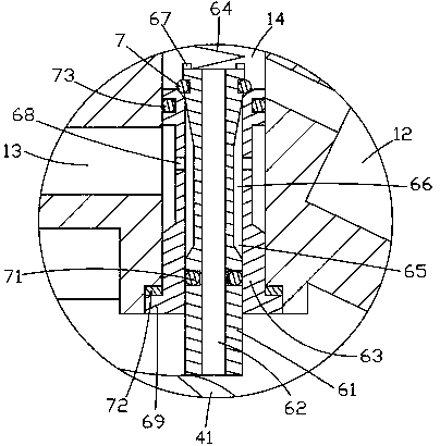
[0031] Figure 1 to Figure 6 It is a structural schematic diagram of the present invention.

[0032] The reference signs are: intake piece 1, body 11, pressure regulating cavity 12, negative pressure channel 13, valve hole 14, handle 15, gas delivery pipe 2, negative pressure generator 3, pressure regulating mechanism 31, pressing handle 4. Top pressing piece 41, intake pipe 5, adsorption piece 51, connector head 52, adsorption cover 53, flange body 54, convex edge 55, control valve 6, valve core 61, air intake channel 62, valve sleeve 63, spring 64. Installation cavity 65, air flow channel 66, spring seat 67, radial hole 68, gland 69, inner sealing ring 7, outer sealing ring 71, sealing gasket 72, upper sealing ring 73, waterproof and breathable parts 8, support ring 81 , waterproof breathable film 82.

[0033] Such as Figure 1 to Figure ...


PUM


Abstract

The invention discloses a tumor taking device for oncology. The tumor taking device includes a gas pipe and a negative pressure generator; the tumor taking device further includes a taking piece, thetaking piece is connected to the negative pressure generator through the gas pipe, and the taking piece includes a body, a press handle and a taking pipe; and the interior of the body is provided witha pressure regulating cavity channel and a negative pressure channel, the body is provided with a valve hole, a control valve is installed in the valve hole, the taking pipe is fixedly connected to the pressure regulating cavity end opening of the pressure regulating cavity channel, the taking pipe communicates with the pressure regulating cavity channel, the press handle is hinged on the body, the press handle can press and cooperate with the valve core of the control valve after being pulled, the valve core is provided with a gas inlet channel along the central axis direction, and the presshandle is provided with a pressing sheet for controlling sealing or opening of the gas inlet channel. The tumor taking device is convenient to use, and uses the negative pressure principle to effectively take and fix tumors without causing tumor rupture.

Description

technical field [0001] The invention relates to the field of medical technology, in particular to a tumor uptaker used in oncology. Background technique [0002] Tumor refers to the new organism formed by the proliferation of local tissue cells under the action of various tumor-causing factors, because this new organism is mostly in the form of space-occupying blocky protrusions, also known as neoplasm. Under the action, a certain cell in the local tissue loses its normal regulation of its growth at the gene level, resulting in abnormal lesions formed by its clonal abnormal proliferation. There are varying degrees of difference. [0003] When a surgeon performs an operation on a patient, the tumor is generally extracted with medical tweezers during tumor resection. However, when the tweezers are used to extract the tumor, there are only two stress points on the tumor and the force area is small. If it is too small, the tumor cannot be clamped. If the force is too large, it...

Claims


Application Information

Patent Timeline
Patent Type & Authority Applications(China)
IPC IPC(8): A61B17/50
CPCA61B17/50
Inventor 卢乐
Owner THE AFFILIATED HOSPITAL OF QINGDAO UNIV
Why Eureka
Try Eureka