Working method of reinforcement cage machining die

A technology for processing molds and working methods, which is applied in the direction of manufacturing tools, wire processing, metal processing equipment, etc., can solve the problems of gap error between the main reinforcement and coil reinforcement, affecting the structural strength of the reinforcement cage, and affecting the welding work, etc.

Active Publication Date: 2020-07-07
贵阳城市建设工程集团有限责任公司
View PDF5 Cites 3 Cited by
  • Summary
  • Abstract
  • Description
  • Claims
  • Application Information

AI Technical Summary

Problems solved by technology

[0003] In the rolling welding process of the existing reinforcement cage, the main reinforcement is affected by gravity when it rotates upwards, and the middle part will bend downwards, so that there will be a gap error between the main reinforcement and the coiled reinforcement, and the main reinforcement will rotate downwards after bending. It will straighten. When the main reinforcement changes from bending to straightening, there will be slippage between the main reinforcement and the coiled reinforcement, which will affect the later welding work and further affect the structural strength of the reinforcement cage. In order to reduce the bending degree of the main reinforcement during movement, a A kind of reinforcement cage processing mold is the technical problem that those skilled in the art need to solve

Method used


Image

  • Working method of reinforcement cage machining die
  • Working method of reinforcement cage machining die
  • Working method of reinforcement cage machining die

Examples


Embodiment Construction

[0022] The following will clearly and completely describe the technical solutions in the embodiments of the present invention with reference to the accompanying drawings in the embodiments of the present invention. Obviously, the described embodiments are only some, not all, embodiments of the present invention. Based on the embodiments of the present invention, all other embodiments obtained by persons of ordinary skill in the art without creative efforts fall within the protection scope of the present invention.

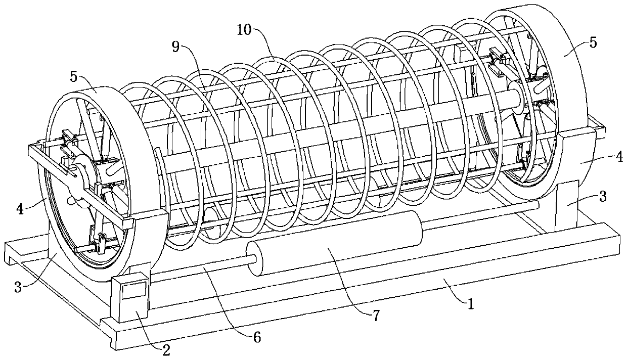
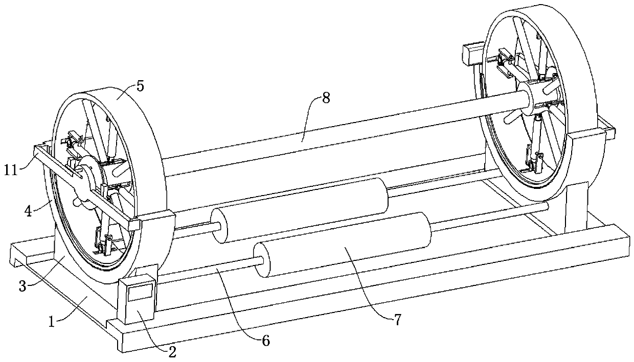
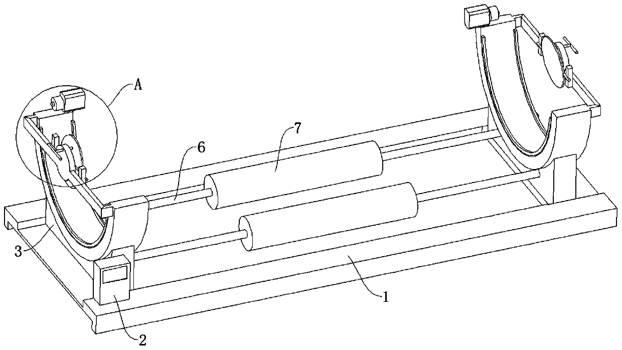
[0023] see Figure 1-9 , the present invention provides a technical solution: a steel cage processing mold, including a base 1, two support blocks 3 are fixedly connected to the top surface of the base 1, the side walls of the support block 3 are fixedly connected to an AFPXHC60T type electric control box 2, and the support block 3 The top is fixedly connected with an arc-shaped slide rail 4, the inner surface of the arc-shaped slide rail 4 is rotatably connected w...


PUM


Abstract

The invention discloses a working method of a reinforcement cage machining die, and relates to the technical field of reinforcement cage machining. A base is included. The top face of the base is fixedly connected with two supporting blocks, the side walls of the supporting blocks are fixedly connected with an electric cabinet, the tops of the supporting blocks are fixedly connected with arc-shaped sliding rails, the inner surfaces of the arc-shaped sliding rails are rotationally connected with rotary rings, the inner surface of each rotary ring is fixedly connected with four connecting rods,one ends of the four connecting rods are fixedly connected with center blocks, the inner surfaces of the two center blocks are fixedly connected with a transmission rod, and the side walls of the arc-shaped sliding rails are fixedly connected with adjusting mechanisms. Through the arrangement of stretching mechanisms, when main ribs move to the tops of the rotary rings, inner sliding blocks push outer sliding blocks to pull fixing rings based on the lever principle, the fixing rings at the two ends of the main ribs are away from each other to achieve a stretching effect, the main ribs are prevented from being bent, the adjusting mechanisms can adjust and stretch the amplitude of the main ribs, and adaptation to main ribs of different specifications is facilitated.

Description

technical field [0001] The invention relates to the technical field of steel cage processing, in particular to a working method for a steel cage processing mold. Background technique [0002] The reinforcement cage refers to the reinforcement structure in the building. Its main function is the same as that of the longitudinal reinforcement of the column. It mainly plays a tensile role. The compressive strength of concrete is high but the tensile strength is very low. To restrain it, so that it can bear a certain horizontal force; in the construction of bridges and culverts or high-rise buildings, piling may be required for the foundation according to requirements. The method is to use machine punching and water mill drilling, and the hole depth meets the design requirements, and then The reinforcement cage is lowered into the pile hole, and then the conduit is inserted for concrete pouring. [0003] In the rolling welding process of the existing reinforcement cage, the main...

Claims


Application Information

Patent Timeline
Patent Type & Authority Applications(China)
IPC IPC(8): B21F27/12B21F27/10B23K37/047
CPCB21F27/121B21F27/10B23K37/047
Inventor 寇引霞朱蓓
Owner 贵阳城市建设工程集团有限责任公司
Why Eureka
Try Eureka