Tube push bench and recyclable construction method of main machine of tube push bench

A construction method and pipe jacking machine technology, applied in earthwork drilling, wellbore lining, tunnel lining, etc., can solve the problems of inability to integrate the shield construction of the sunken pump room and difficult recovery of the main engine, so as to achieve less personnel and reliable construction. The effect of controlling and preventing gushing

Active Publication Date: 2020-09-08
CHINA RAILWAY ENGINEERING EQUIPMENT GROUP CO LTD
View PDF8 Cites 10 Cited by
  • Summary
  • Abstract
  • Description
  • Claims
  • Application Information

AI Technical Summary

Problems solved by technology

[0007] In view of the deficiencies in the above-mentioned background technology, the present invention proposes a recyclable construction method for a pipe jacking machine and its main engine, which solves the problem that the existing pipe jacking machine cannot carry out shield tunneling construction on the integrated sunken pump room in the communication channel. The technical problem that the host is difficult to recover

Method used


Image

  • Tube push bench and recyclable construction method of main machine of tube push bench
  • Tube push bench and recyclable construction method of main machine of tube push bench
  • Tube push bench and recyclable construction method of main machine of tube push bench

Examples


Embodiment 1

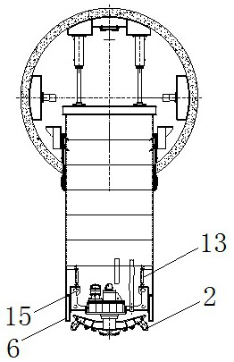
[0053] Embodiment 1, a kind of pipe jacking machine, such as figure 1 with figure 2 As shown, the shield body 6 is included, and the cutter head system driven by the host is arranged in the shield body 6 . The main engine includes a motor 5 or a hydraulic motor, which drives a main shaft 3 through a reducer 4, and the front end of the main shaft 3 is connected with a conical cutterhead 1, and a hob 19 and a side scraper 2 are arranged on the conical cutterhead 1.

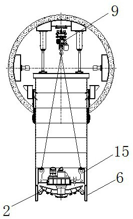
[0054] A platform 21 is provided on the outside of the shield body 6 , and a pushing system cooperating with the shield body 6 is provided on the top of the platform 21 . Under the action of the rotary drive of the main engine and the vertical thrust of the jacking system, the conical cutter head 1 rotates downward to excavate the soil.

[0055] A shield inner sleeve 15 is detachably connected to the shield body 6 , the main engine is fixedly arranged in the shield inner sleeve 15 , and the front end of the shiel...

Embodiment 2

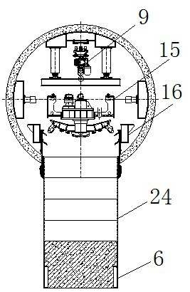
[0060] Embodiment 2, a pipe jacking machine, the shield body 6 is connected to the upper end of the inner sleeve 15 of the shield through a connecting baffle plate 14 with bolts. The connecting baffle 14 can transmit the thrust from the vertical shoe 22 to the main engine; at the same time, after the downward construction is completed, the connecting baffle 14 is removed, and the shield body 6 and the inner sleeve 15 of the shield are separated, and the pipe jacking machine can be realized. Host recycling.

[0061] Other structures of this embodiment are the same as those of Embodiment 1.

Embodiment 3

[0062] Embodiment 3, a pipe jacking machine, a recovery oil cylinder 13 is arranged between the shield body 6 and the inner sleeve 15 of the shield, when the connecting baffle 14 is removed and the shield body 6 and the inner sleeve 15 of the shield are separated, The recovery oil cylinder 13 can conveniently realize the separation of the shield body 6 and the sleeve 15 in the shield body.

[0063] Further, one end of the recovery oil cylinder 13 is hinged to the inner wall of the shield body 6 , and the other end is hinged to the upper end of the inner sleeve 15 of the shield.

[0064] Other structures of this embodiment are the same as Embodiment 1 or 2.


PUM


Abstract

The invention discloses a tube push bench and a recyclable construction method of a main machine of the tube push bench. The technical problems that an existing tube push bench cannot perform shield construction on an integrated sinking type pump house in a contact channel and the main machine is difficult to recycle are solved. The tube push bench comprises a shield, a host-driven cutter system is arranged in the shield, and a shield inner sleeve is detachably connected into the shield. The main machine is arranged in the shield inner sleeve, an outer edge tool is arranged at the outer edge of the cutter system, the outer edge tool is circumferentially and fixedly connected with the cutter system and axially downwards and one-way rotatably hinged to the cutter system, a rack is arranged outside the shield, and a pushing system matched with the shield is arranged at the top of the rack. The tube push bench is wide in application range, high in safety and high in construction efficiency.

Description

technical field [0001] The invention belongs to the technical field of integrated sinking pump room construction equipment, in particular to a recyclable construction method of a pipe jacking machine and its main engine. Background technique [0002] With the rapid development of the city, the above-ground space becomes more and more limited. The development of underground space is an inevitable trend of future urban development. Tunnel engineering has developed into an important project in the process of underground space development. Construction of communication passages and pump rooms between tunnels. At present, the pump room in the communication channel has a built-in pump room and an integrated sunken pump room. Since the built-in pump room is shallow in depth, easy to collect sand, and needs to be equipped with high-performance water pumps, the integrated sunken pump room has the advantages of Broad application prospects. [0003] At present, for the construction o...

Claims


Application Information

Patent Timeline
Patent Type & Authority Applications(China)
IPC IPC(8): E21D9/08E21D9/12E21D9/14E21D11/10
CPCE21D9/08E21D9/0642E21D9/0607E21D11/10E21D9/12E21D9/14
Inventor 叶蕾贺飞孙磊蒋鹏鹏孙英杰董艳萍王小涛徐德帆
Owner CHINA RAILWAY ENGINEERING EQUIPMENT GROUP CO LTD
Why Eureka
Try Eureka