Spraying wastewater treatment equipment

A technology for wastewater treatment and equipment, which is applied in the field of spraying wastewater treatment equipment, and can solve problems such as time-consuming and expensive

Inactive Publication Date: 2020-10-23
合肥乡情园林景观设计有限公司
View PDF5 Cites 2 Cited by
  • Summary
  • Abstract
  • Description
  • Claims
  • Application Information

AI Technical Summary

Problems solved by technology

[0009] The purpose of the present invention is to provide a traditional spraying wastewater treatment equipment to solve the time-consuming problem th

Method used


Image

  • Spraying wastewater treatment equipment
  • Spraying wastewater treatment equipment
  • Spraying wastewater treatment equipment

Examples


Embodiment 1

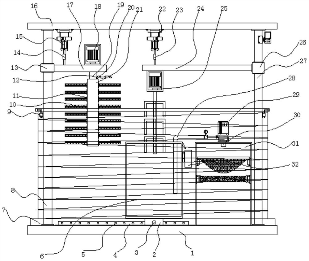
[0035]Example 1: See Figure 1-6 , a spraying wastewater treatment equipment, comprising a base 1 and a top plate 16, the top of the base 1 is fixedly connected with an anti-splash structure 7, and one side of the top of the inner base 1 of the anti-splash structure 7 is fixedly connected with a first support column 8, and the anti-splash structure 7 The other side of the top of the inner base 1 is fixedly connected with the second support column 27, the top of the first support column 8 and the top of the second support column 27 are fixedly connected with the top plate 16, and the bottom end of the top plate 16 is fixedly connected with the first hydraulic cylinder 15 , the model of the first hydraulic cylinder 15 can be J64RT2UNIVER, the bottom end of the first hydraulic cylinder 15 is fixedly connected with the first telescopic rod 14, the outside of the first support column 8 is provided with a first sliding sleeve 13, the first sliding sleeve 13 One side of the first sup...

Embodiment 2

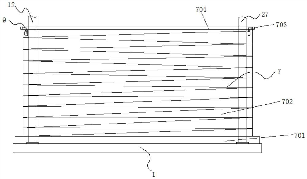
[0039] Embodiment 2: The anti-splash structure 7 is composed of a placement slot 701, a telescoping cover 702, an insert block 703 and a fixing bar 704. The bottom end of the placement slot 701 is fixedly connected to the top of the base 1, and the inside of the placement slot 701 is fixedly connected with a telescopic cover. 702, the top of the telescopic cover 702 is fixedly connected with a fixed bar 704, and both sides of the fixed bar 704 are fixedly connected with an insert block 703;

[0040] The insert block 703 is embedded in the slot 9, and an engaging structure is formed between the insert block 703 and the slot 9;

[0041] Specifically, such as figure 1 and image 3 As shown, before the wastewater treatment, the telescopic cover 702 is first taken out from the inside of the placement slot 701, and then the insert block 703 is inserted into the inside of the slot 9 through the engaging relationship between the insert block 703 and the slot 9 Just fix it so that wh...

Embodiment 3

[0042] Embodiment 3: The stirring mechanism 25 is composed of a housing 2501, a second drive motor 2502, a stirring shaft 2503 and a stirring blade 2504, the top of the housing 2501 is fixedly connected to the bottom of the second support plate 24, and the inside of the housing 2501 is set There is a second driving motor 2502, the model of the second driving motor 2502 can be Y90L-2, the output end of the stirring shaft 2503 is fixedly connected with the stirring shaft 2503, and the outer wall of the stirring shaft 2503 is fixedly connected with the stirring blade 2504;

[0043] The size of the stirring blades 2504 is the same, the stirring blades 2504 are "L" shaped, and the stirring blades 2504 are arranged in four rows on the outer wall of the stirring shaft 2503;

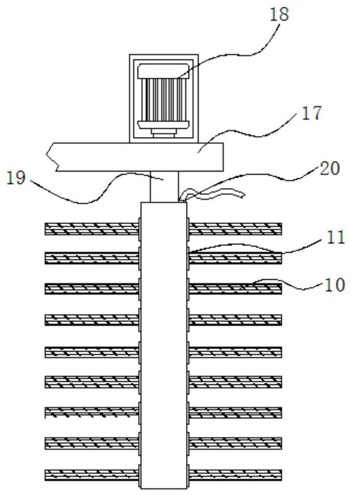
[0044] Specifically, such as figure 1 and Figure 4 As shown, since the stirring blades 2504 are arranged in four rows on the stirring shaft 2503, the stirring blades 2504 are in an "L" shape, the second drive ...


PUM


Abstract

The invention discloses spraying wastewater treatment equipment and particularly relates to the technical field of spraying wastewater treatment. The spraying wastewater treatment equipment comprisesa base and a top plate, the top end of the base is fixedly connected with an anti-splashing structure, a first supporting column is fixedly connected to one side of the top end of the base in the anti-splashing structure, a second supporting column is fixedly connected to the other side of the top end of the base in the anti-splashing structure, a top plate is fixedly connected to the top ends ofthe first supporting column and the second supporting column, a first hydraulic air cylinder is fixedly connected to the bottom end of the top plate, and a first telescopic rod is fixedly connected tothe bottom end of the first hydraulic air cylinder. The scum collecting structure is composed of a drainage groove, a collecting box, a fixing block and a mounting groove. Due to the fact that the drainage groove is obliquely formed in one side of the top end of the box body, dross is pushed into the collecting box at the bottom of the drainage groove through a tool, then the fixing block is taken out of the mounting groove, the dross in the collecting box is cleaned away, and the interior of the pipe body cannot be blocked.

Description

technical field [0001] The invention relates to the technical field of spraying wastewater treatment, in particular to a spraying wastewater treatment equipment. Background technique [0002] Spraying wastewater is one of the most difficult industrial wastewaters. It has the characteristics of large chroma and strong toxicity. If the spraying wastewater is not treated, it will easily pollute the surrounding environment. The existing spraying wastewater treatment equipment still has some problems when it is working. Not solved, so we need to improve a kind of spraying wastewater treatment equipment. [0003] In the process of realizing the present invention, the inventors have found that at least the following problems in the prior art have not been resolved: [0004] (1) The traditional spraying wastewater treatment equipment is not equipped with the function of preventing wastewater from splashing, resulting in that the wastewater is easily splashed to the outside during s...

Claims


Application Information

Patent Timeline
IPC IPC(8): C02F9/04C02F103/14
CPCC02F9/00C02F1/5281C02F1/001C02F1/283C02F2201/002C02F2201/004C02F2303/02C02F2303/14C02F2303/16C02F2103/14
Inventor 孙朋
Owner 合肥乡情园林景观设计有限公司
Why Eureka
Try Eureka