Check patentability & draft patents in minutes with Patsnap Eureka AI!

A transformer moisture absorber transfer valve

A technology of moisture absorber and transfer valve, applied in the field of transformers, can solve the problems of few spare parts, mismatched installation size, low quality of elimination, etc., and achieve the effect of improving service life, good sealing performance and long service life

Active Publication Date: 2021-11-09
HUZHOU ELECTRIC POWER SUPPLY CO OF STATE GRID ZHEJIANG ELECTRIC POWER CO LTD
View PDF0 Cites 0 Cited by
  • Summary
  • Abstract
  • Description
  • Claims
  • Application Information

AI Technical Summary

Problems solved by technology

In order to ensure that the pressure in the oil tank will not be too high, the design requires that the upper layer of the oil conservator be connected to the outside air. However, when the humidity of the outside air is high, moisture will enter the oil conservator and pollute the transformer oil. When it exceeds the standard value of 20mg / L, it will lead to adverse consequences such as a decrease in the insulation performance of the transformer oil and excessive dielectric loss, which will eventually lead to insulation breakdown and serious safety accidents such as short circuits. Therefore, connecting pipes and moisture absorbers will be installed on the oil conservator. The pipe and dehumidifier communicate with the outside air
[0004] The national standard for dehumidifiers "DL / T1386-2014 Guidelines for Selection of Dehumidifiers for Power Transformers" implemented in 2015 stipulates that the diameter of the connecting flange of the dehydrating absorber is 85mm, that is, the hole distance of the connecting flange is 6cm, while the old model in the substation The installation size of the connecting flange of the dehumidifier is 115mm in diameter, that is, the hole distance of the connecting flange is 8cm. The size of the hole is the same, resulting in a mismatch between the installation size of the connecting pipe and the new dehumidifier, and the production of the old dehumidifier has been discontinued, there are few spare parts, and the quality of the elimination is low, resulting in a higher defect frequency of the old dehumidifier than the new dehumidifier High, increasing the workload of substation operation and maintenance personnel

Method used


Image

  • A transformer moisture absorber transfer valve
  • A transformer moisture absorber transfer valve
  • A transformer moisture absorber transfer valve

Examples


Embodiment 1

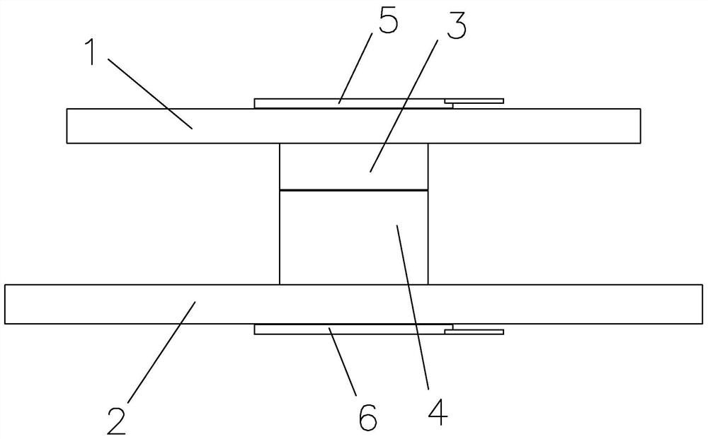
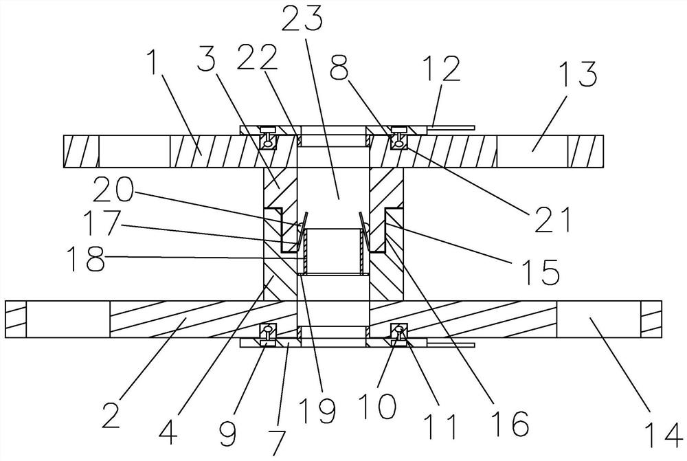
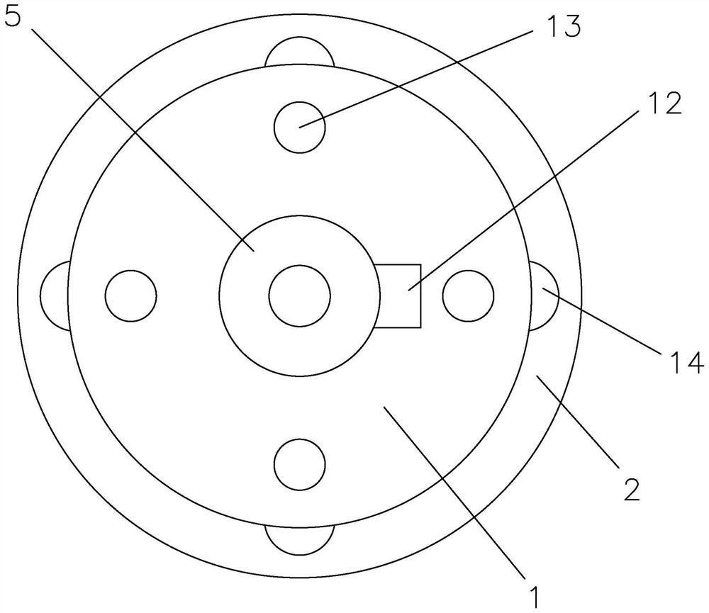
[0023] Such as figure 1 , 2 , 3, a transformer moisture absorber transfer valve, including the first connection plate 1 for connecting with the flange on the moisture absorber and the second connection plate 2 for connecting with the flange on the connecting pipe, the first A connecting plate 1 is provided with a first connecting hole 13 matching with the flange hole on the dehumidifier, and a second connecting plate 2 is provided with a second connecting hole 14 matching with the flange hole on the connecting pipe. The first connecting plate 1 is consistent with the design standard of the flange of the dehumidifier, and the second connecting plate 2 is consistent with the design standard of the connecting pipe flange, so that after two-two connection, the installation of the new dehumidifier is realized. The first connecting plate 1 and the second connecting plate The two connection plates 2 are connected through the main connection cylinder, and the main connection cylinder...


PUM


Abstract

The invention relates to the field of transformers, in particular to a transfer valve for a transformer moisture absorber. A transfer valve for a transformer moisture absorber, comprising a first connection plate and a second connection plate, the first connection plate and the second connection plate are connected through a main connection cylinder, the main connection cylinder, the first connection plate and the second connection plate Moisture absorption holes are correspondingly arranged between them, a first sealing gasket is arranged on the first connecting plate, and a second sealing gasket is arranged on the second connecting disk, both the first sealing gasket and the second sealing gasket include a sealing body, and the sealing body One side is provided with a snap ring, the first connecting plate and the second connecting plate are provided with annular grooves, the sealing body is provided with a compressed air chamber, and the snap ring is provided with an expansion chamber, and the compressed air chamber and the expansion chamber are provided with an air guide channel connect. The invention can connect the novel moisture absorber and the connecting pipe, and has good sealing performance.

Description

technical field [0001] The invention relates to the field of transformers, in particular to a transfer valve for a transformer moisture absorber. Background technique [0002] The dehumidifier for transformer is mainly used to remove and dry the debris and moisture in the air entering the oil conservator in the transformer due to the change of transformer oil temperature, so as to maintain the insulation strength of transformer oil. [0003] The function of the oil conservator is to adjust the volume change of the transformer oil when the temperature changes. When the oil temperature rises, the oil volume becomes larger and the oil level on the oil conservator rises. When the oil temperature decreases, the oil volume becomes smaller. , the oil level in the oil conservator will drop. In order to ensure that the pressure in the oil tank will not be too high, the design requires that the upper layer of the oil conservator be connected to the outside air. However, when the humi...

Claims


Application Information

Patent Timeline
Patent Type & Authority Patents(China)
IPC IPC(8): F16L29/00H01F27/14
CPCF16L29/00H01F27/14
Inventor 陈超徐凯戴则维钱晓杰王钢辉凌秋阳殷文宣王云龙王宇明陈昱成华义李小康
Owner HUZHOU ELECTRIC POWER SUPPLY CO OF STATE GRID ZHEJIANG ELECTRIC POWER CO LTD
Features
  • R&D
  • Intellectual Property
  • Life Sciences
  • Materials
  • Tech Scout
  • Unparalleled Data Quality
  • Higher Quality Content
  • 60% Fewer Hallucinations
Learn More