
Valve tower of DC circuit breaker
A technology of DC circuit breaker and valve tower, which is applied in the direction of converting AC power input to DC power output, cable installation, emergency protection circuit devices, etc. And other issues
- Summary
- Abstract
- Description
- Claims
- Application Information
AI Technical Summary
Problems solved by technology
Method used
Image

Examples
Embodiment Construction
[0022] The present invention will be described in further detail below in conjunction with the accompanying drawings and specific embodiments.
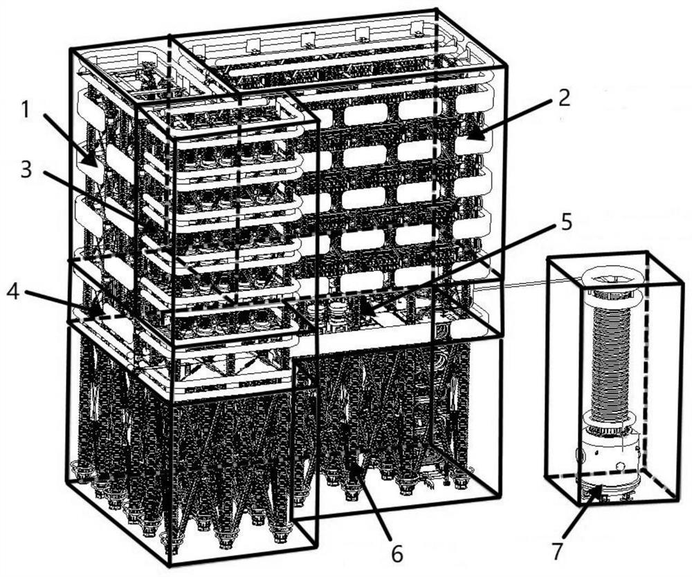
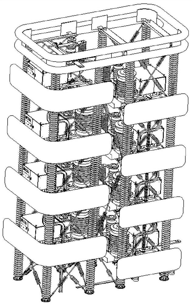
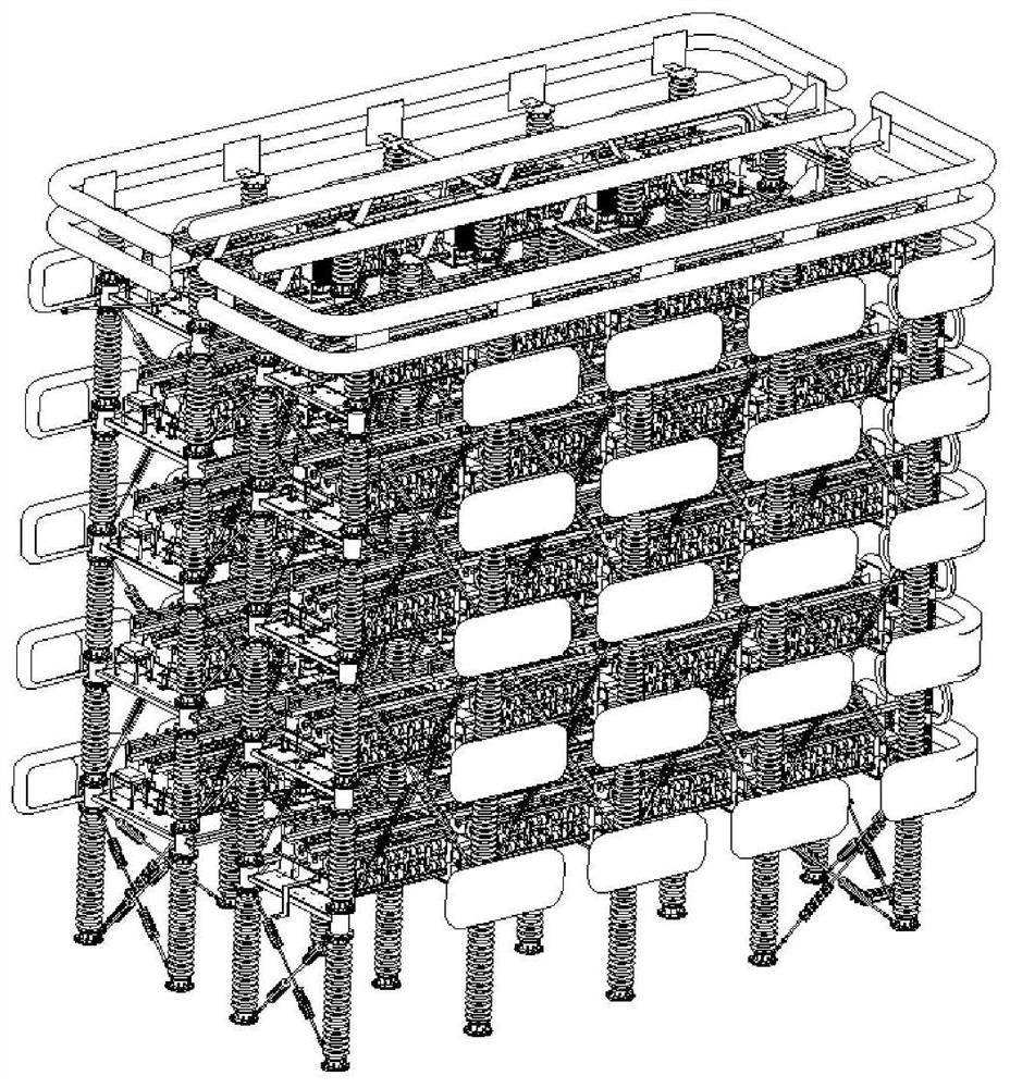
[0023] Such as figure 1 As shown, a valve tower of a DC circuit breaker includes: a fast mechanical switch tower 1, a power electronic switch tower 2, an energy consumption lightning arrester tower 3, a coupling negative pressure drive device 5, an insulating support platform 6 and an isolation transformer 7; The support platform 6 is arranged at the bottom of the valve tower, and the top of the insulating support platform 6 is provided with a transition layer 4. The fast mechanical switch tower 1, the power electronic switch tower 2, the energy consumption arrester tower 3, and the coupling negative pressure drive device 5 are all installed on the transition layer 4, the coupling negative pressure drive device 5 is located inside the power electronic switch tower 2, the fast mechanical switch tower 1, the power electronic switch towe...
PUM
 Abstract
Description
Claims
Application Information