Molded hose joint assembly

A technology for hose joints and hose fittings, applied in the direction of pipes/pipe joints/pipes, hose connection devices, pipe connection arrangements, etc., can solve the damage to the stability of sealing components, wrapping, and increase in cooling time of plastic molding materials And other issues

Inactive Publication Date: 2003-09-03
THE GATES CORP
View PDF1 Cites 2 Cited by
  • Summary
  • Abstract
  • Description
  • Claims
  • Application Information

AI Technical Summary

Problems solved by technology

However, this method also has disadvantages: a relatively large amount of molding material is usually used to seal the entire connection portion of the assembly, and such use of material will reduce the cost savings and often compromise the integrity of the seal or the stability of the assembly
The disadvantages of this approach are: relative to the prior art, it increases the possibility of independent rotation of different hoses; The outer cover seals the hose connection and the body of the entire inner connector
Also...

Method used


Image

  • Molded hose joint assembly
  • Molded hose joint assembly
  • Molded hose joint assembly

Examples


Embodiment Construction

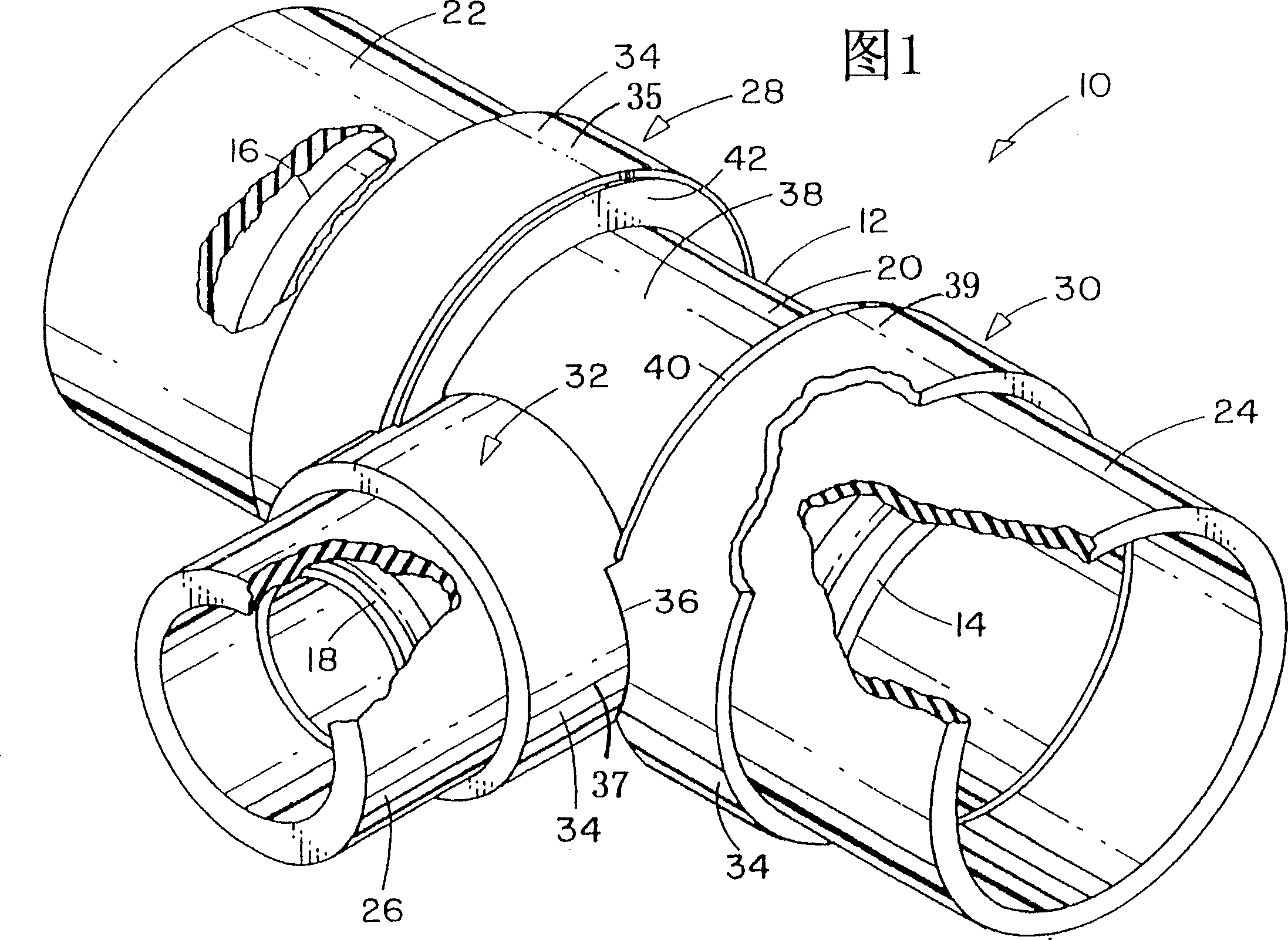
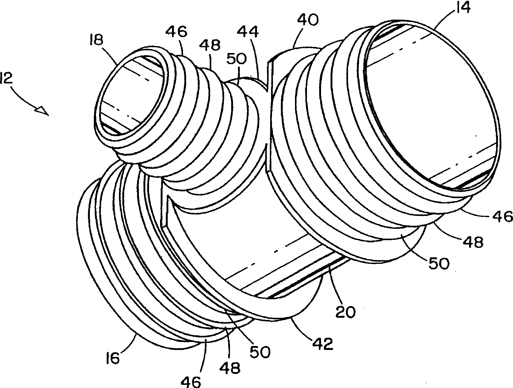
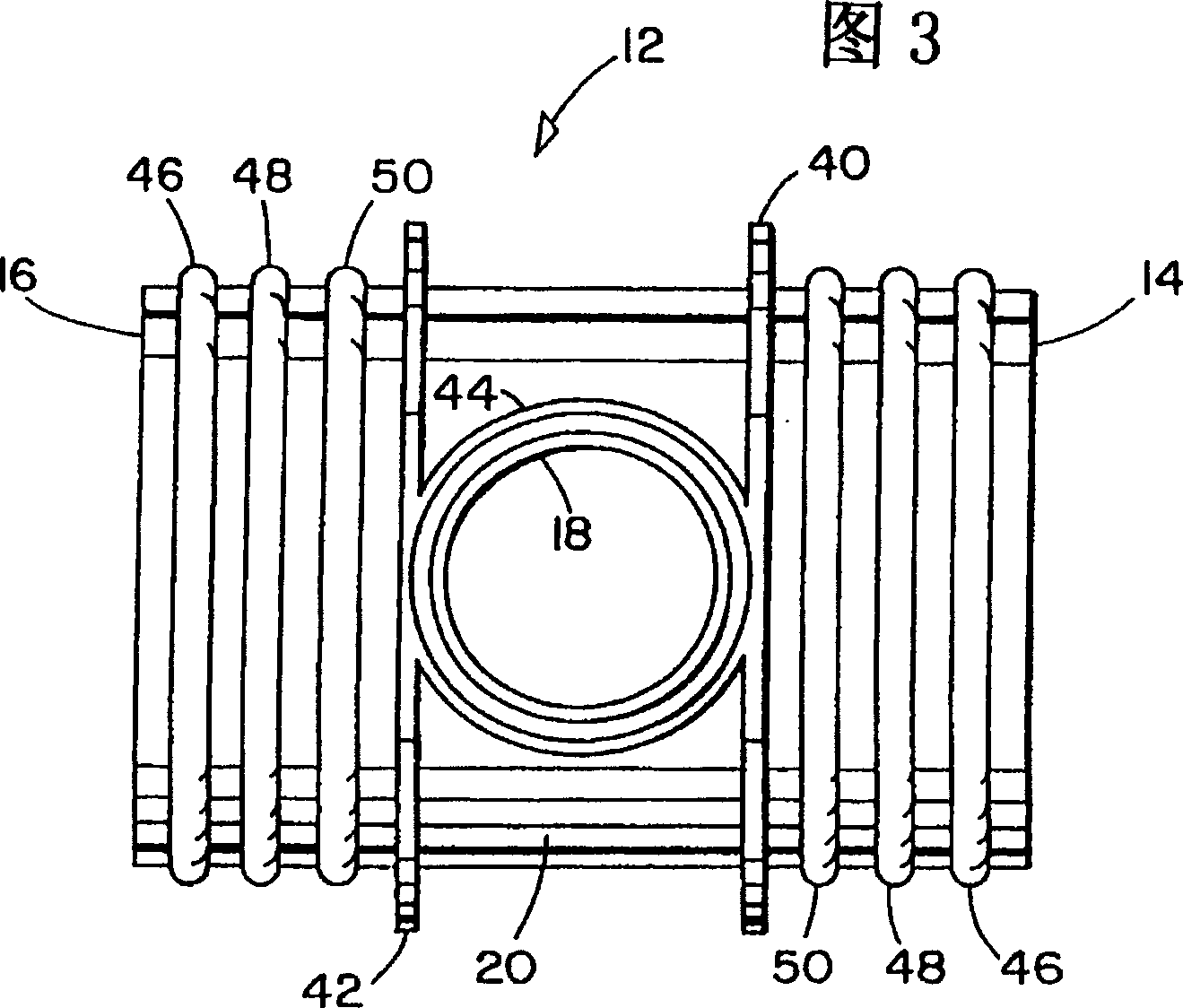
[0020] Referring to Figure 1, there is shown an embodiment of the present invention of a "T" shaped hose coupling assembly. In the illustrated embodiment, the hose coupling assembly 10 includes a substantially rigid inner connector 12 having at least two ends defining hose connection ports 14, 16, and in the illustrated embodiment additionally There is also a rod-shaped mouth 18 of this kind. The inner connector 12 includes a body portion 20 . The assembly also includes at least two flexible hoses 22, 24, 26, each flexible hose 22, 24, 26 is connected to the hose connection port 14, 16, 18 at the end of the inner connector 12 to form a soft Tube connections 28, 30, 32.

[0021] The assembly also includes an outer cover 34 that engages with a portion of the circumference of at least one of the hose connections 28, 30, 32 of each hose 22, 24, 26 to substantially seal the hoses 22, 24, 26 is sealed with the inner connector 12. The hose coupling assembly 10 is characterized in...


PUM

PropertyMeasurementUnit
Thicknessaaaaaaaaaa

Abstract

Molded hose joint assemblies, e.g., connections, branched hoses and bleeding devices for fluid circuits, and especially such assemblies for use in automotive and industrial coolant circuit assemblies, which assemblies comprise a reduced amount of molded outer covering element over prior art designs, said covering element substantially encapsulating the connection points of generally flexible hose ends to generally rigid inner connection members. The outer covering element forms a unitary mass or interconnecting rings about at least two such hose connection points. Flexible manufacturing techniques for producing such assemblies are provided.

Description

Technical field: [0001] The present invention relates to hose coupling assemblies, such as connectors, branch hoses and suction devices for fluid circuits, in particular to hose coupling assemblies used in automotive and industrial coolant circuits, the invention also relates to It relates to a method of manufacturing the hose fitting assembly. Background technique [0002] Hose coupling assemblies, especially those used in fluid circuits on automotive and / or industrial processes, operate in extremely harsh environments. Factors such as varying pressures and temperatures in different parts of the assembly, different diameters of the different hoses in a particular loop, and exposure to chemical materials place stringent requirements on hose assemblies. For the system to work effectively, the sealed connection between the hose and the inner connector must be watertight and prevent separation due to fluid pressure. This type of separation is called bursting. The environment...

Claims


Application Information

Patent Timeline
IPC IPC(8): F16L33/22F16L31/00F16L33/24F16L33/34F16L41/02F16L47/32
CPCF16L31/00F16L33/245F16L33/34F16L47/32F16L41/00
Inventor 基思·M·克劳斯梅尔文·L·马里奥特
Owner THE GATES CORP
Why Eureka
Try Eureka