Machine vision detection equipment

A technology of machine vision detection and detection equipment, which is applied in the direction of instruments, measuring devices, scientific instruments, etc., can solve the problem of non-adjustable display height and display angle of display components, reduce the probability of mismatching work habits and improve work comfort , the effect of flexible adjustment

Pending Publication Date: 2020-12-11
YANCHENG INST OF TECH
View PDF9 Cites 1 Cited by
  • Summary
  • Abstract
  • Description
  • Claims
  • Application Information

AI Technical Summary

Problems solved by technology

[0002] As we all know, machine vision inspection equipment is a device that uses machines instead of human eyes for measurement and judgment. It converts the ingested target into an image signal through machine vision products, and sends it to a dedicated image processing system. According to pixel distribution and brightness, Information such as color is converted into digital signals. The image system performs various operations on these signals to extract the characteristics of the target, and then controls the product quality according to the results of the discrimination. It has been widely used in the field of industrial production; now Some machine vision inspection equipment includes a detection equipment body. The top of the detection equipment body is provided with an image acquisition mechanism, a display component and a conveying mechanism. A penetration hole is provided through the top area of ​​the left end of the detection equipment body. It is located at the bottom of the penetration hole, and the image acquisition mechanism is located directly above the conveying mechanism; when the existing machine vision inspection equipment is used, first install the inspection equipment body at the designated position and complete the debugging, then the conveying mechanism can convey the product to be inspected directly below the image acquisition mechanism, and then the image acquisition mechanism collects image information and transmits it to the detection equipment body for image processing, and then the detection equipment body transmits the processed image information to the display component, at this time the staff Product quality can be judged; in the use of existing machine vision inspection equipment, it is found that different workers have different working habits, so the requirements for the display height and display angle of the display components are different. However, the display height and display angle of the existing display components It is not adjustable, so there is a high probability that the display height and display angle of the display components will not match the working habits of the staff. At this time, it is easy to make the staff tired, resulting in poor practicability

Method used


Image

  • Machine vision detection equipment
  • Machine vision detection equipment
  • Machine vision detection equipment

Examples


Embodiment Construction

[0019] The specific implementation manners of the present invention will be further described in detail below in conjunction with the accompanying drawings and embodiments. The following examples are used to illustrate the present invention, but are not intended to limit the scope of the present invention.

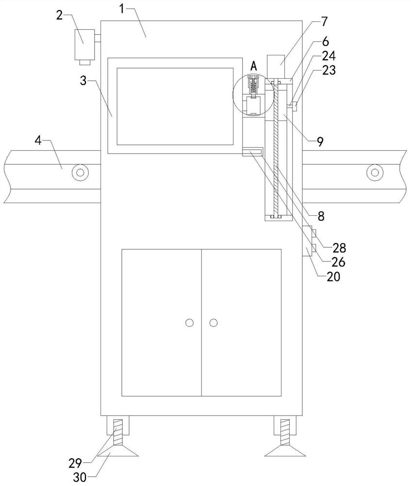
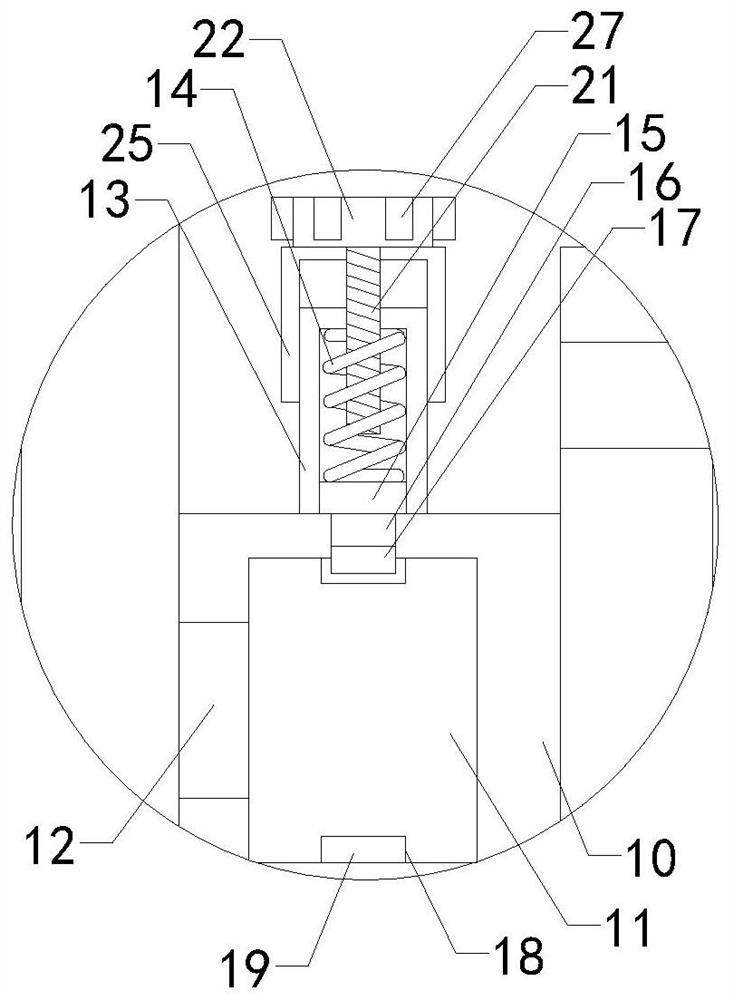
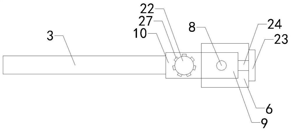
[0020] Such as Figure 1 to Figure 5 As shown, a machine vision detection device of the present invention includes a detection device body 1, an image acquisition mechanism 2, a display assembly 3 and a conveying mechanism 4 are arranged on the top of the detection device body 1, and the left end top area of ​​the detection device body 1 is set through There is a penetration hole 5, the conveying mechanism 4 passes through the penetration hole 5 and is located at the bottom of the penetration hole 5, and the image acquisition mechanism 2 is located directly above the conveying mechanism 4; it also includes a limit plate 6, a motor assembly 7, a power threaded rod 8, Slide...


PUM


Abstract

The invention relates to the technical field of detection equipment accessory devices, in particular to machine vision detection equipment which can flexibly adjust the display height and the displayangle of a display assembly according to the working habits of different workers. Therefore, the probability that the display height and the display angle of the display assembly are not matched withthe working habits of workers is reduced, and the working comfort of the workers is improved; the detection equipment comprises a detection equipment body, an image acquisition mechanism, a display assembly and a conveying mechanism are arranged at the top of the detection equipment body, a through hole is formed in the top area of the left end of the detection equipment body in a penetrating mode, the conveying mechanism penetrates through the through hole and is located at the bottom of the through hole, and the image acquisition mechanism is arranged over the conveying mechanism; the equipment further comprises a limiting plate, a motor assembly, a power threaded rod, a sliding block, a driving shaft, a rotating block, a connecting shaft, a control rod, a control spring, an extrusion plate, a pin rod and a three-edged pin head, a limiting groove is formed in the left end of the limiting plate, and a rotating cavity is formed in the driving shaft.

Description

technical field [0001] The present invention relates to the technical field of inspection equipment attachments, in particular to a machine vision inspection equipment. Background technique [0002] As we all know, machine vision inspection equipment is a device that uses machines instead of human eyes for measurement and judgment. It converts the ingested target into an image signal through machine vision products, and sends it to a dedicated image processing system. According to pixel distribution and brightness, Information such as color is converted into digital signals. The image system performs various operations on these signals to extract the characteristics of the target, and then controls the product quality according to the results of the discrimination. It has been widely used in the field of industrial production; now Some machine vision inspection equipment includes a detection equipment body. The top of the detection equipment body is provided with an image ac...

Claims


Application Information

Patent Timeline
Patent Type & Authority Applications(China)
IPC IPC(8): G01N21/84
CPCG01N21/84
Inventor 林鑫焱刘玮耿龙伟郭俊王辉陈勇徐忠华万益东经成程锦
Owner YANCHENG INST OF TECH
Why Eureka
Try Eureka