Building construction steel bar positioning device

A positioning device and building construction technology, applied in construction, building components, building reinforcements, etc., can solve the problems of poor project quality, inability to locate main bars, unqualified spot inspection of construction projects, etc., and achieve convenient operation, space saving, and energy saving The effect of transport difficulty

A positioning device and building construction technology, applied in construction, building components, building reinforcements, etc., can solve the problems of poor project quality, inability to locate main bars, unqualified spot inspection of construction projects, etc., and achieve convenient operation, space saving, and energy saving The effect of transport difficulty

CN113235823AActive Publication Date: 2021-08-10SHANGHAI GREENLAND CONSTR GRP

Image

  • Building construction steel bar positioning device
  • Building construction steel bar positioning device
  • Building construction steel bar positioning device

Examples


Embodiment 1

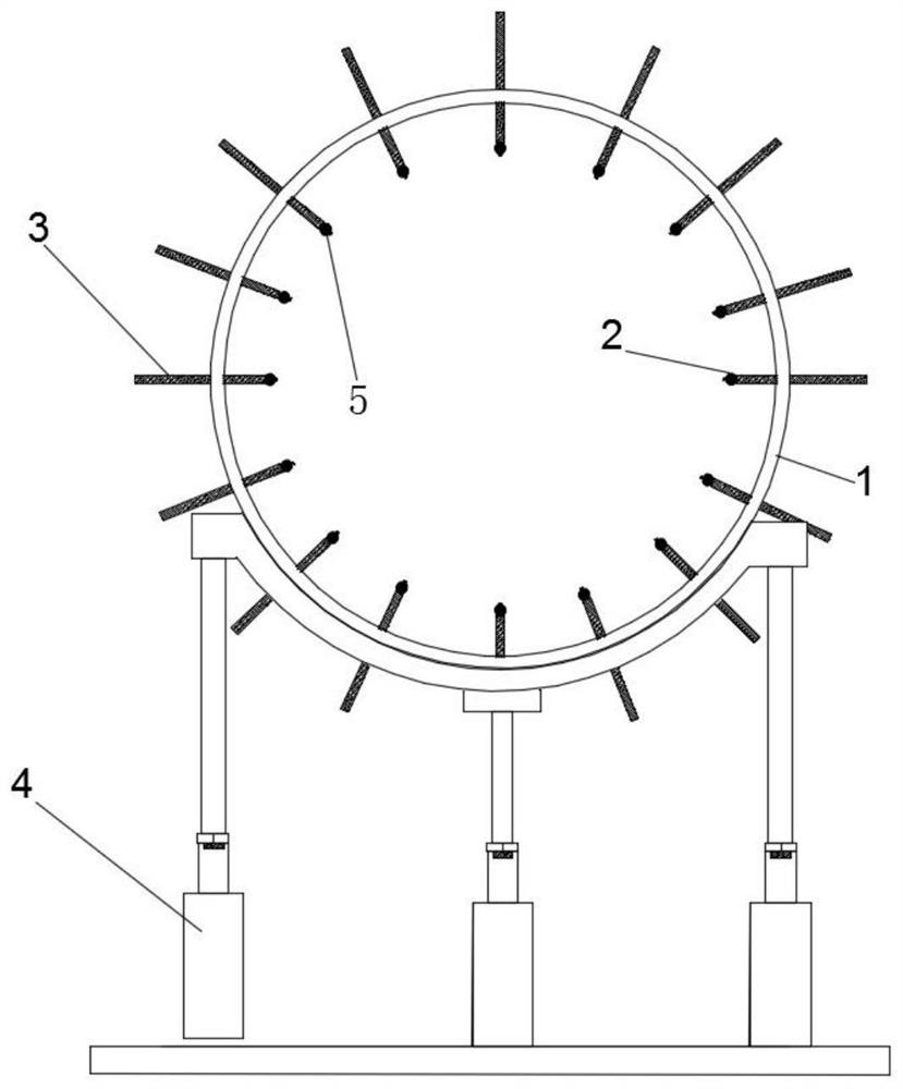
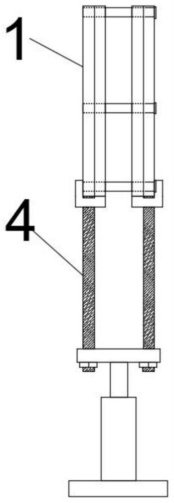
[0038] Embodiment 1: with reference to attached Figure 1-15A kind of building construction reinforcing bar positioning device shown, comprises positioning plate 1, if positioning frame 4 and some steel bar positioning structures, positioning plate 1 is installed on the positioning frame 4, and the reinforcing bar positioning structure is movable installed on the positioning plate 1; The disk 1 includes two positioning rings 11 and several connecting rods 12 arranged symmetrically. The connecting rods 12 are installed between the two positioning rings 11 to connect the two positioning rings 11, and form an Chute 14; described reinforcing bar positioning structure comprises positioning sleeve 2 and positioning rod 3, and the lower end of positioning sleeve 2 is provided with sleeve protrusion 23, and sleeve protrusion 23 is connected with an end of positioning rod 3, and positioning rod 3 is movable It is arranged in the chute 14 and installed in the chute 14 through nuts; the ...

Embodiment 2

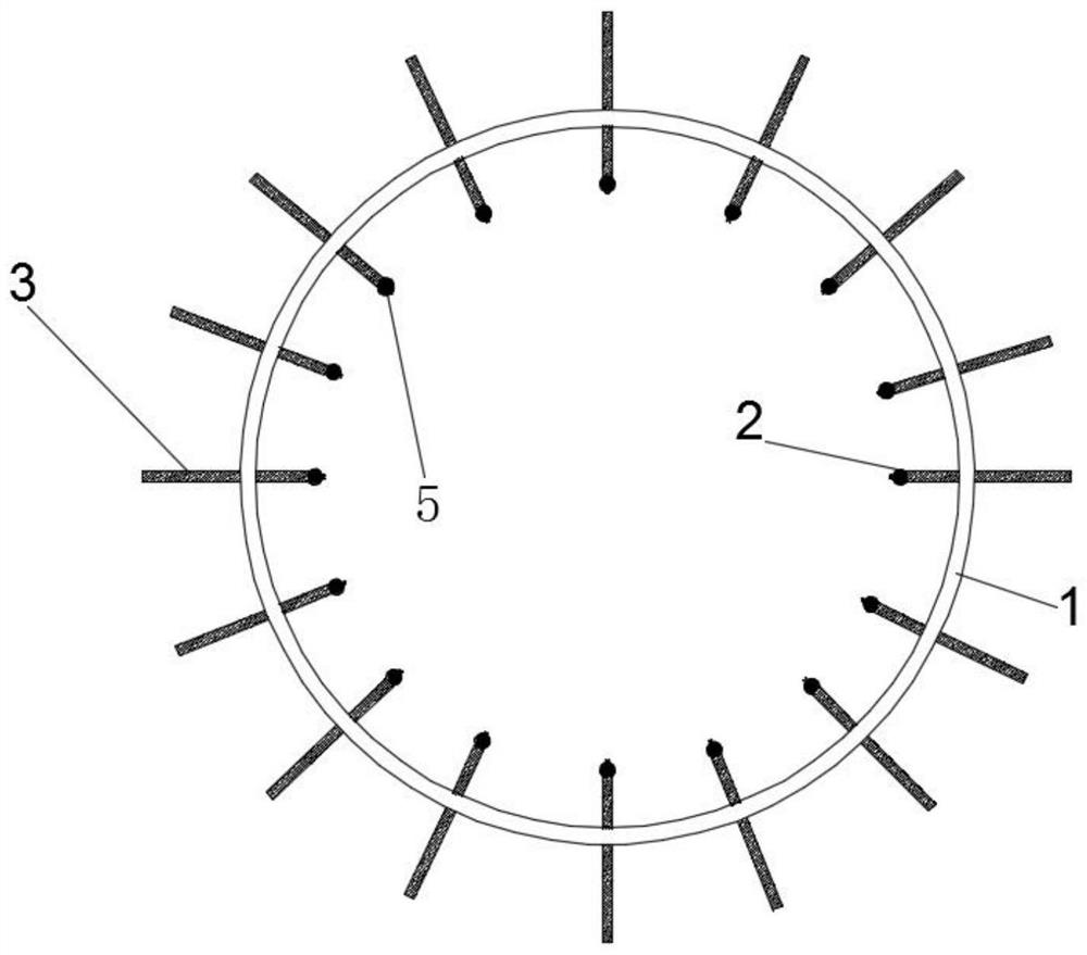
[0052] Embodiment 2: as attached Figure 16 As shown, different from Embodiment 1, Embodiment 1 describes the situation that the positioning sleeve 2 is set in the positioning disc 1, but in reality, due to the different environments used, when the diameter of the steel cage to be bound is larger than the positioning When the diameter of the disk 1 is different, we can set the positioning sleeve 2 on the outside of the positioning disk 1 to locate the steel bar 5, so that the device can meet the construction requirements of steel cages with different diameters.

[0053] The method of use and the principle of use of the building construction reinforcing bar positioning device described in the above two embodiments are as follows:

[0054] (1) First of all, according to the terrain position and the length of the steel cage, select the number of steel bar positioning devices required for construction, position them, and perform rough leveling on the construction site, and if poss...


PUM


Abstract

The invention discloses a building construction steel bar positioning device. The building construction steel bar positioning device comprises a positioning disc, a plurality of steel bar positioning structures and a positioning frame; the positioning disc is installed on the positioning frame, and the steel bar positioning structures are movably arranged on the positioning disc; the positioning disc comprises two symmetrically arranged positioning rings and a plurality of connecting rods, the connecting rods are arranged between the two positioning rings, and a sliding groove is formed between the two connected positioning rings; each steel bar positioning structure comprises a positioning sleeve and a positioning rod; the lower end of the positioning sleeve is provided with a sleeving protrusion, the sleeving protrusion is connected with the corresponding positioning rod, and the other end of the positioning rod is movably arranged in the corresponding sliding groove; and the positioning frame comprises a bottom plate and a positioning mechanism, and the positioning mechanism is arranged on the bottom plate. According to the device, the positioning disc is arranged to be of a detachable structure and is assembled for use during use, space is saved, and transportation difficulty is lowered; the steel bar positioning structures can position and support main bars, the binding precision of a steel reinforcement cage is guaranteed, and the building construction steel bar positioning device has the advantages of being convenient to use, reasonable in structure and capable of greatly shortening the construction process and improving the construction quality.

Description

technical field [0001] The invention relates to the technical field of building construction equipment, in particular to a positioning device for steel bars in building construction. Background technique [0002] With the development of my country's economy and technology, my country's infrastructure construction is developing at an extremely fast speed, and as we know, the construction of infrastructure is inseparable from the continuous improvement and innovation of construction equipment; [0003] In the process of engineering construction, steel bars are the main skeleton of building facilities. The accurate positioning of steel bars often affects the quality of engineering construction. Use specific equipment to locate the position of the main reinforcement to ensure the spacing of the main reinforcement and the binding quality, so as to complete the high-quality construction process and improve the overall quality of the construction project; [0004] At present, the ...

Claims


Application Information

Patent Timeline
10 Aug 2021
Publication
CN113235823A
IPC
E04C5/16
CPC
E04C5/16
Inventors
罗政; 李先缘