A kind of coring device and coring method

A technology of coring device and coring bit is applied in the direction of extracting undisturbed core device, valve device of wellbore/well, earthwork drilling, etc. It can solve problems such as ball valve stuck, and achieve the effect of accurate results and simple structure.

Active Publication Date: 2022-03-29
SOUTHWEST PETROLEUM UNIV
View PDF19 Cites 0 Cited by
  • Summary
  • Abstract
  • Description
  • Claims
  • Application Information

AI Technical Summary

Problems solved by technology

[0004] The purpose of the present invention is to solve the problem that the rock core is easy to get stuck when the ball valve is closed, and to provide a coring device and a coring method. The ball valve is stuck to realize in-situ fidelity coring, so as to ensure the accuracy of the calculation results of oil and gas reserves

Method used


Image

  • A kind of coring device and coring method
  • A kind of coring device and coring method
  • A kind of coring device and coring method

Examples


Embodiment 1

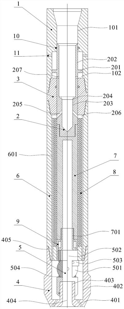
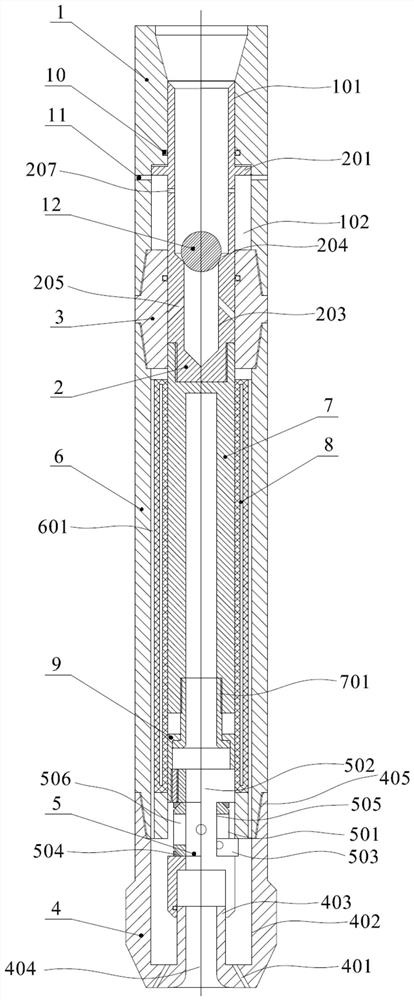
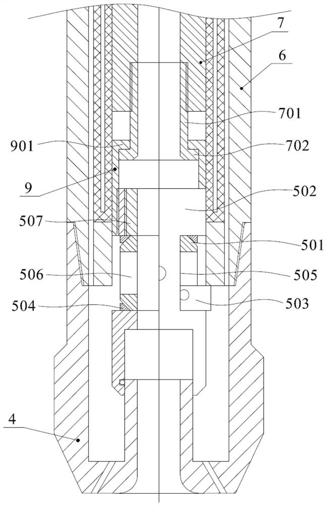
[0033] figure 1 It is a schematic diagram of the state of the coring device opening the ball valve, figure 2 It is a schematic diagram of the state of the coring device closing the ball valve, image 3 Yes figure 2 Enlarged view of one end of the coring bit of the middle coring device, see Figure 1-Figure 3 As shown, the coring device includes an upper connecting button 1 , an outer coring cylinder 6 and a coring drill 4 which are connected in sequence. The upper connection buckle 1 is used to connect the power device to provide drilling power. The upper buckle has an axially arranged inner hole 101 , the inner hole 101 of the upper buckle 1 , the inner hole of the outer core barrel 6 and the inner hole 402 of the core drill 4 . The first shaft hole is formed in communication. The core drill 4 is provided with a drill inner hole 402 , the bottom surface of the drill inner hole 402 is provided with a core hole 404 , and one end of the hole of the drill inner hole 402 is...

Embodiment 2

[0035] The difference between the coring device in embodiment 1 and the coring device in embodiment 2 lies in the lifting mechanism. see Figure 1-Figure 3 As shown, the lifting mechanism includes a convex ring 201 arranged on the outer wall of the differential lifting rod 2, a ring groove 102 is formed on the inner wall of the inner hole 101 of the buckle, and the outer diameter of the convex ring 201 is the same as that of the The diameters of the annular grooves 102 are equal. The convex ring 201 is arranged in the ring groove 102 , and the differential lift rod 2 is provided with a second communication hole 207 , and the second communication hole 207 is located on the convex ring 201 close to the core bit 4 On one side, the second communication hole 207 communicates with the inner hole 101 of the buckle, the side wall of the ring groove 102 is provided with a second drain hole 11, and the second drain hole 11 is located in the convex ring 201 is away from the side of the...

Embodiment 3

[0039] see Figure 1-Figure 3 As shown, on the basis of Embodiment 2, the inner wall of the outer coring cylinder 6 is provided with a vacuum thermal insulation sleeve 8, which further heats and insulates the inner coring cylinder 7. The upper connection buckle 1 and the outer core-taking cylinder 6 are connected by a connecting head 3 . Both ends of the connecting head 3 have a tapered structure, and two ends of the core-taking outer cylinder 6 are provided with tapered holes to be threadedly connected to the connecting head 3 . The connecting groove 206 is formed on the connecting head 3 and the outer coring cylinder 6 , or the connecting head 3 and the bottom surface of the taper hole of the outer core 6 are spaced to form the connecting groove 206 . The coring outer cylinder 6 and the coring bit 4 are threadedly connected. The chamfering of the mouth of the inner hole 402 of the drill bit forms a tapered hole structure 404, the two ends of the outer core-taking cylinder ...


PUM


Abstract

The invention discloses a coring device and a coring method. The coring device includes an upper connecting buckle, a coring outer cylinder and a coring drill bit connected in sequence, the inner hole of the connecting buckle of the upper connecting buckle, the The inner hole of the core outer cylinder and the inner hole of the core bit are connected to form a first shaft hole, and a detachable valve, a slidable differential lifting rod, and a valve connected to the first shaft hole are arranged in the first shaft hole. The core-taking inner cylinder of the differential lifting rod, the core-taking hole of the core-taking drill bit communicates with the core-taking inner cylinder through the valve, and the differential lifting rod is also connected with a lifting mechanism, and the lifting mechanism can drive The differential lifting rod and the coring inner cylinder are separated from the valve by a certain distance and the valve is closed; the coring method includes putting in a sealing ball to make the lifting mechanism drive the differential lifting rod to rise. In the present invention, the valve is closed after the rock core is away from the valve for a certain distance, which avoids the problem that the valve is stuck by the rock core, and improves the reliability of heat preservation and pressure-holding coring.

Description

technical field [0001] The invention relates to the technical field of oil and gas exploration coring, in particular to a coring device and a coring method. Background technique [0002] Rock core is the most intuitive and reliable valuable information reflecting the underground sedimentary environment. When conducting rock mechanics test research, usually the rock or core is taken out first and processed into standard specimens before testing. However, after the core is taken out from the in-situ environment, some components of the core are oxidized after being exposed to the outside air, the original pressure is released, and the oil, gas and water in the core are volatilized and lost due to the change of the original pressure and temperature of the formation. , the physical properties of the rock will also be destroyed. In order to make the oil and gas characteristics of the core consistent with the real situation of the formation, and to ensure the accurate calculation ...

Claims


Application Information

Patent Timeline
Patent Type & Authority Patents(China)
IPC IPC(8): E21B25/00E21B25/10E21B34/06E21B10/60E21B21/00
CPCE21B25/00E21B25/10E21B34/06E21B10/605E21B21/00
Inventor 敬佳佳邱志礼邱晨昊唐曦何航宇
Owner SOUTHWEST PETROLEUM UNIV
Why Eureka
Try Eureka